
Magnetic resistance suspension centrifugal type device

A centrifugal and magnetic levitation technology, applied in the field of biomedical engineering, can solve the problems of high heat generation and energy consumption, poor reliability and large volume, and achieve the effect of reducing volume, high reliability and reducing current consumption

Active Publication Date: 2015-01-28
SHANDONG UNIV OF SCI & TECH
View PDF5 Cites 9 Cited by
  • Summary
  • Abstract
  • Description
  • Claims
  • Application Information

AI Technical Summary

Problems solved by technology

[0004] In order to solve the problems of large volume, high heat generation, high energy consumption, and poor reliability of the third-generation artificial heart assist device, the present invention proposes a magnetic-resistive suspension centrifugal device by comprehensively applying magnetic levitation control technology and bearingless switched reluctance motor technology , using a symmetrically distributed permanent magnet structure to achieve non-contact suspension, reducing the power consumption of the control system, with the advantages of small size, simple structure, and long service life

Method used


Image

  • Magnetic resistance suspension centrifugal type device
  • Magnetic resistance suspension centrifugal type device

Examples


Embodiment Construction

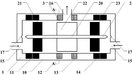
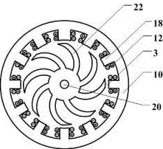
[0015] The present invention is mainly composed of a magnetic levitation stator 1, a magnetic levitation rotor 2, and a gap 3. The magnetic levitation stator 1 includes: a stator housing 10, a left radial magnetization permanent magnet array 11, a left coil winding 12, a right coil winding 13, and a right radial magnetization Permanent magnet array 14, liquid input port 15, liquid output port 16, concave port 17, motor stator core 18; the magnetic levitation rotor 2 includes: rotating shaft 20, left radially magnetized permanent magnet ring 21, motor rotor core blades 22, right radially magnetized permanent magnet ring 23. The liquid input port 15 is at the left and right sides of the magnetic levitation stator 1, and the liquid output port 16 is at the center position on the upper side of the magnetic levitation stator 1. The liquid enters the magnetic levitation device through the liquid input port 15, and is driven by the rotor iron core blade 22 of the motor, from the liqui...


PUM


Abstract

The invention belongs to the technical field of biomedical engineering and relates to an artificial heart auxiliary device, in particular to a magnetic resistance suspension centrifugal type device which comprises three parts, namely a stator (1), a magnetic suspension rotor (2) and a clearance (3), wherein a left diametrical magnetization permanent magnet array (11) and a right diametrical magnetization permanent magnet array (14) are in a circular ring shape and are nested at the left and right sides of the inner wall of the magnetic suspension stator (1); a left coil winding (12) and a right coil winding (13) are positioned at the center of the inner side of the magnetic suspension stator (1); a left diametrical magnetization permanent magnet ring (21) and a right diametrical magnetization permanent magnet ring (23) are fixedly arranged on the left and right sides of a rotating shaft (20); a motor rotor iron core blade (22) is fixedly arranged at the middle of the rotating shaft (20), is in a bent tooth shape and is formed by laminating silicon steel sheets. The magnetic resistance suspension centrifugal type device can be used for solving the problems of large size and high power consumption of a third-generation artificial heart auxiliary device and has the advantages of simple structure, flexibility in control, high in reliability and the like.

Description

technical field [0001] The invention belongs to the technical field of biomedical engineering, and relates to an artificial heart assist device, in particular to a magnetic resistance suspension centrifugal device. Background technique [0002] The heart is the power source of human blood circulation. Cardiovascular diseases have become a hot spot in the medical field. Heart transplantation is an important way to treat critical heart disease patients. However, the demand for the heart far exceeds the supply, and artificial heart assist devices have emerged. . The first-generation artificial heart assist device uses mechanical or electromagnetic drive to generate periodic volume changes to simulate the beating of the heart. It has a large volume, complex structure, and short life; the second-generation artificial heart assist device uses mechanical bearings to support the high-speed rotating impeller. Due to friction, blood wear, heat generation, induced hemolysis, thrombus ...

Claims


Application Information

Patent Timeline
Patent Type & Authority Applications(China)
IPC IPC(8): A61M1/12
CPCA61M2210/125A61M60/148A61M60/40A61M60/50
Inventor 孙传余肖林京李波文艺成
Owner SHANDONG UNIV OF SCI & TECH
Learn More