Reflow welding process of DIP through-hole part

A technology of reflow soldering and soldering tools, which is applied in the direction of welding equipment, welding equipment, manufacturing tools, etc. It can solve the problems of uncontrollable tin amount in solder joints, poor tin dipping, and insufficient tin amount in solder joints, so as to reduce costs and man-hours , Avoid the abnormal occurrence of empty welding and improve the welding quality of solder joints

Inactive Publication Date: 2015-01-28
昆山圆裕电子科技有限公司
View PDF7 Cites 8 Cited by
  • Summary
  • Abstract
  • Description
  • Claims
  • Application Information

AI Technical Summary

Problems solved by technology

However, wave soldering has the following defects: 1. Using wave furnace automatic welding or small tin furnace automatic welding, the product welding surface and parts PIN are easily polluted by flux FLUX, resulting in abnormal product function (inability to conduct); 2. Wave peak Common welding defects in the furnace: the amount of tin in the solder joints cannot be controlled: the incorrect delivery angle of the tin furnace will cause the solder joints to be too large, and the inclination angle is from 1 to 7 degrees. Thin tin will cause insufficient tin content of solder joints and poor tin deficiency such as tin holes. Thick tin will cause short circuit between two solder joints and poor soldering and other tin defects; white residue: flux used for too long or the composition Caused by deterioration; Poor soldering: Some parts or special FPC boards (such as KeyPAD key boards) cannot be avoided by tools, which will cause a high risk of poor soldering; 3. Excessive cost investment: each group is soldered by a wave furnace All products need to be welded with fixtures (carriers), so the larger the product volume, the higher the cost of welding fixtures, and the long-term high-temperature impact of the fixtures in use will greatly reduce their service life; 4. Complicated operations The cumbersome operation process directly affects the production capacity of each group of products and consumes a lot of man-hours

Method used


Image

  • Reflow welding process of DIP through-hole part
  • Reflow welding process of DIP through-hole part

Examples


Embodiment Construction

[0025] The present invention will be further described below in conjunction with specific embodiments.

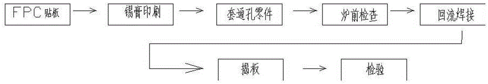
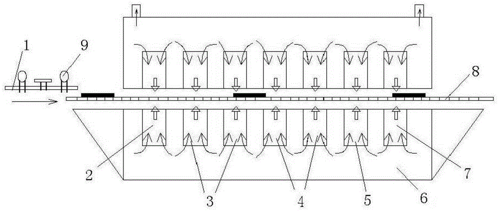
[0026] Such as figure 1 , figure 2 As shown, the reflow soldering process of a kind of DIP through-hole parts of the present invention comprises automatic printing machine (not shown), hot air reflow soldering machine (not shown) and supporting welding equipment (not shown), comprising the following steps: 1 ) Pre-soldering preparation: prepare the printed circuit board 1 for soldering, the DIP through-hole parts 9 of the chip components and the welding tools, and make the powdery solder, flux, and adhesive into a paste solder paste, and the solder paste is Sn96 .5Ag3.0Cu0.5 solder paste alloy; printed circuit board 1 is provided with back glue, which plays the role of fixing parts and substrates, and avoids floating height and empty welding abnormalities during the welding process; welding tools include circuit board tools and fixtures; 2) tin printing and placement: pu...


PUM


Abstract

The invention discloses a reflow welding process of a DIP through-hole part and belongs to the technical field of manufacturing of printed circuit boards. The reflow welding process relates to an automatic printing machine, a hot air reflow welding machine and matched welding equipment, and comprises the following steps of (1) pre-welding preparation, (2) tin printing and mounting, (3) pre-welding assembly, (4) in-furnace welding and (5) post-welding test, wherein Sn96.5Ag3.0Cu0.5 tin paste alloy is adopted as tin paste in the step (1). Compared with a conventional DIP process product, the reflow welding process has the advantages that the cleaning time of a flux is eliminated, the risks of residue of the flux and pollution of the product are zero, the production efficiency is improved by 50 percent; the one-time welding yield can exceed 99.5 percent, the welding quality of a welding point is effectively improved, the production efficiency is improved, the cost is reduced, and the labor time is shortened.

Description

technical field [0001] The invention belongs to the technical field of printed circuit board manufacturing, and more specifically relates to the reflow soldering process of DIP through-hole parts. Background technique [0002] Due to the continuous miniaturization of printed circuit boards of electronic products, chip components have appeared, and the traditional welding method can no longer meet the needs. First of all, the reflow soldering process is adopted in the assembly of hybrid integrated circuit boards. Most of the components assembled and welded are chip capacitors, chip inductors, mount transistors and diodes. With the improvement of the entire technology of SMT, the emergence of a variety of chip components (SMC) and mount devices (SMD), the reflow soldering process technology and equipment as part of the mounting technology have also been developed accordingly, and its application is becoming more and more extensive. It has been applied in almost all fields of ...

Claims


Application Information

Patent Timeline
Patent Type & Authority Applications(China)
IPC IPC(8): B23K1/008B23K3/00H05K3/34
CPCB23K1/012B23K1/20B23K31/125B23K2101/42H05K3/34
Inventor 吴冬平郭跃
Owner 昆山圆裕电子科技有限公司
Why Eureka
Try Eureka