
Vehicle active suspension actuator with energy self-supply function and its control method

A technology for actuator controllers and active suspensions, applied to suspensions, elastic suspensions, vehicle components, etc., which can solve the problems of ineffective active control of actuators, frequent switching speeds, shock absorption effects and their control laws issues such as design constraints

Active Publication Date: 2015-09-02
XIAN UNIV OF SCI & TECH
View PDF5 Cites 0 Cited by
  • Summary
  • Abstract
  • Description
  • Claims
  • Application Information

AI Technical Summary

Problems solved by technology

The liquid-electric energy-feeding shock absorber can only work in the energy feedback mode. By adjusting the current of the generator, the electromagnetic resistance torque of the generator is adjusted, thereby adjusting the damping force of the entire suspension system. What it essentially accomplishes is In the control process of semi-active suspension, because there is no output of active control force, the shock absorption effect and the design of control law are limited, and it will also affect the ride comfort of the vehicle and the improvement of handling stability.
[0004] In addition, the control methods of energy self-supply active suspension actuators in the prior art often focus on a certain aspect of the performance of the active suspension, without the overall performance of the comprehensive energy self-supply active suspension actuator, resulting in the actuator being The active control effect is not obvious during the working process, and the switching speed between the energy feedback mode and the active control mode is too frequent, which causes a serious hysteresis effect in the system and has a great impact on the life of the battery; The control method of the motor speed in the device needs to be improved, and the existing technology cannot make the active suspension in the best vibration reduction state.

Method used


Image

  • Vehicle active suspension actuator with energy self-supply function and its control method
  • Vehicle active suspension actuator with energy self-supply function and its control method
  • Vehicle active suspension actuator with energy self-supply function and its control method

Examples


Embodiment Construction

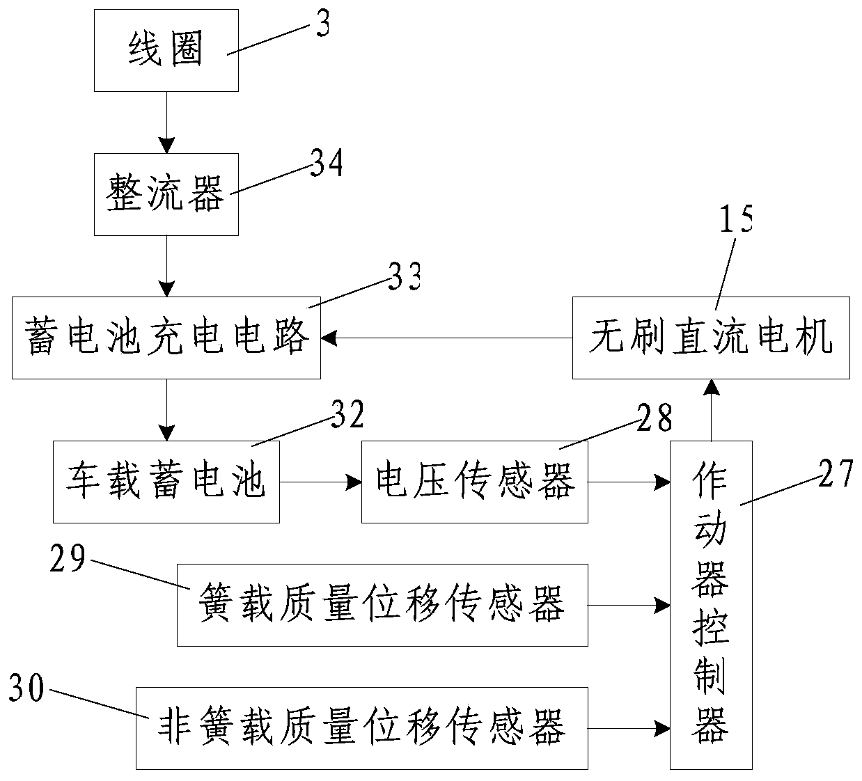
[0095] Such as figure 1 and figure 2 As shown, the vehicle active suspension actuator with energy self-supply function of the present invention includes an actuator body and an actuator controller 27, and the input terminal of the actuator controller 27 is connected with a vehicle battery 32 The voltage sensor 28 for detecting the output voltage of the sprung mass displacement sensor 29 for detecting the sprung mass displacement and the unsprung mass displacement sensor 30 for detecting the unsprung mass displacement. 32 is connected with a battery charging circuit 33; the actuator body includes an outer sleeve 10 and a guide rod 1, the top of the outer sleeve 10 is fixedly connected with a guide sleeve 16, and the lower part of the outer sleeve 10 is set with a second An inner sleeve 7, the upper part of the outer sleeve 10 is fitted with a second inner sleeve 17, and the inner middle part of the outer sleeve 10 is sealed and connected with the first inner sleeve 7 and the ...


PUM


Abstract

The invention discloses a vehicle active suspension actuator with an energy self-supplying function. The vehicle active suspension actuator with the energy self-supplying function comprises an outer sleeve, a guide rod, a guiding sleeve, a first inner sleeve, a second inner sleeve and a first guiding and sealing device, wherein the bottom of the guide rod is connected with a piston; the middle upper portion of the guide rod is connected with a permanent magnet; a coil is wound on the second inner sleeve; a baffle is arranged on the inner lower portion of the outer sleeve; a brushless direct-current motor is arranged on the inner bottom of the outer sleeve; a hydraulic pump is arranged on the top of the baffle; the inner lower portion of the first inner sleeve is connected with a second guiding and sealing device; a rotating shaft of the brushless direct-current motor is connected with a rotating shaft of a hydraulic pump; a first oil opening of the hydraulic pump is in threaded connection with a threaded hole; an upper through hole is formed in the upper portion of the first inner sleeve; and a lower through hole is formed in a section, which is positioned between the baffle and the second guiding and sealing device, of the first inner sleeve. The invention also discloses a control method for the vehicle active suspension actuator with the energy self-supplying function. By the vehicle active suspension actuator with the energy self-supplying function and the control method for the vehicle active suspension actuator with the energy self-supplying function, the service life of a vehicle-mounted storage battery can be prolonged, and an active suspension can be in an optimum vibration reduction state.

Description

technical field [0001] The invention belongs to the technical field of automobile suspension systems, and in particular relates to a vehicle active suspension actuator with energy self-supply function and a control method thereof. Background technique [0002] When the car is running on the road, the relative displacement between the sprung mass and the unsprung mass of the car will occur due to the unevenness of the road surface and the acceleration, deceleration, and steering of the car, which will cause the car to vibrate. The shock absorber in the traditional passive suspension converts this part of mechanical energy into heat energy in the form of friction and dissipates it, thereby generating a damping force to attenuate the vibration of the car. At the same time, due to the fixed parameters such as stiffness and damping of the traditional passive suspension, it can only ensure that the car can achieve the best performance under a specific road state and driving speed,...

Claims


Application Information

Patent Timeline
Patent Type & Authority Patents(China)
IPC IPC(8): B60G17/0195B60G17/018
Inventor 寇发荣
Owner XIAN UNIV OF SCI & TECH
Learn More