Air powered vehicle

An aerodynamic vehicle and compressed air technology, applied to electric vehicles, vehicle parts, electric traction, etc., can solve the problems of low cost, long life, high reliability, etc., and achieve the effect of low cost and simple structure

Inactive Publication Date: 2015-01-28
SUZHOU SAIPA SOLAR TECH CO LTD
View PDF6 Cites 8 Cited by
  • Summary
  • Abstract
  • Description
  • Claims
  • Application Information

AI Technical Summary

Problems solved by technology

[0006] Although all kinds of new energy vehicles and aerodynamic vehicles are emerging in an endless stream, there is no pure aerodynamic vehicle with a simple structure that is all-electric, fully-electrically controlled, has high reliability, low cost, long life, and convenient construction of auxiliary facilities.

Method used


Image

  • Air powered vehicle
  • Air powered vehicle

Examples


Embodiment 1

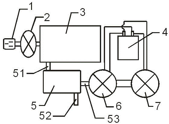
[0019] The DC motor 7 drives the vehicle forward by driving the front axle and the rear axle.

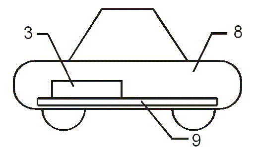
[0020] In this embodiment, the frame body 9 is arranged in the vehicle frame 8, and the air compressor 2, the compressed air tank 3, the backup battery 4, the fluid power engine 5, the DC generator 6, and the DC motor 7 are arranged on the vehicle frame 8, The air compressor 2 is connected with the power cord 1, and the compressed air tank 3 is provided with an engine air inlet 51, and the compressed air tank 3 is connected with the fluid power engine 5 through the engine air inlet 51, and the fluid power engine 5 passes through the engine drive shaft 53 Drive the DC generator 6 to generate electricity, and the exhaust gas after working in the fluid power engine 5 is discharged through the engine exhaust port 52. The DC generator 6 is connected to the backup battery 4 and the DC motor 7 respectively, and the backup battery 4 is connected to the DC motor 7. The DC motor 7 is two, is ...

Embodiment 2

[0023] The DC motor 7 advances by directly driving the wheels.

[0024]In this embodiment, the frame body 9 is arranged in the vehicle frame 8, and the air compressor 2, the compressed air tank 3, the backup battery 4, the fluid power engine 5, the DC generator 6, and the DC motor 7 are arranged on the vehicle frame 8, The air compressor 2 is connected with the power cord 1, and the compressed air tank 3 is provided with an engine air inlet 51, and the compressed air tank 3 is connected with the fluid power engine 5 through the engine air inlet 51, and the fluid power engine 5 passes through the engine drive shaft 53 Drive the DC generator 6 to generate electricity, and the exhaust gas after working in the fluid power engine 5 is discharged through the engine exhaust port 52. The DC generator 6 is connected to the backup battery 4 and the DC motor 7 respectively, and the backup battery 4 is connected to the DC motor 7. The DC motor 7 is four, and four DC motors 7 are respectiv...


PUM


Abstract

The invention relates to an air powered vehicle comprising a power supply plugging wire, an air compressor, a compressed air tank, an auxiliary battery, a fluid power engine, direct-current engines, a direct-current motor, an engine gas inlet, an engine gas outlet, an engine drive shaft, a frame and a frame body. According to the air powered vehicle, an existing hybrid power vehicle or pure electric vehicle is optimized, fuel power equipment is omitted, an electric drive system is retained, the majority of batteries are detached, and the space for installing the batteries and an oil tank is used for installing the compressed air tank. During inflation, the power supply plugging wire is connected to a power supply or ordinary power supply socket, after the air compressor is connected to the power supply through the power supply plugging wire, and the compressed air tank is inflated; when the four direct-current engines of a vehicle body are connected to four wheels of the vehicle body respectively, a differential is further omitted, and the vehicle is an actual four-wheel drive vehicle and a complete electric powered and controlled vehicle without a mechanical transmission system.

Description

technical field [0001] The invention relates to the field of new energy vehicles, in particular to aerodynamic vehicles. Background technique [0002] Today's energy crisis is becoming more and more imminent. Some analysts say that if gasoline cannot be replaced by new energy sources in the next few decades, then cars will be a dying "biology". At the same time, most of the culprits of air pollution such as smog come from the use of fuel vehicles. The air pollution in China's major cities has reached an unbearable level. Although electric vehicles can solve the problem of air pollution, the charging time of electric vehicles is long 3. The driving distance is short, and the cost will increase exponentially if the driving mileage of a general car is to be achieved. Moreover, the fuel tank of fuel vehicles and the battery of electric vehicles will also burn and explode after a violent collision, and the safety performance cannot be guaranteed. Most importantly, the productio...

Claims


Application Information

Patent Timeline
Patent Type & Authority Applications(China)
IPC IPC(8): B60L11/02B60L50/10
CPCB60L50/10Y02T10/7072
Inventor 俞忠良林筱华俞琦
Owner SUZHOU SAIPA SOLAR TECH CO LTD
Why Eureka
Try Eureka