Drainage and seepage type felting composite structure

A combined structure and pavement technology, applied to water supply devices, pavement details, waterway systems, etc., can solve problems such as difficult surface heat exchange, difficulty in large-scale promotion, and impossibility of water collection and utilization, so as to reduce urban heat island effect and construction and easy maintenance, cost-effective results

Inactive Publication Date: 2015-01-28
深圳市致道景观有限公司
View PDF4 Cites 16 Cited by
  • Summary
  • Abstract
  • Description
  • Claims
  • Application Information

AI Technical Summary

Problems solved by technology

[0002] The traditional pavement structure of roads and squares is composed of base, surface and cushion, all of which require on-site construction machinery to pave, roll, and lay the base and surface. There are many on-site construction procedures, and the operating procedures of each process are complicated. , the biggest disadvantage is that it is impermeable, airtight, and difficult for surface heat exchange.
Since the 1990s, the use of permeable materials to replace traditional materials for pavement has been widely used in urban construction in developed countries. At present, domestic research on material-based permeable pavements focuses on permeable brick pavements and permeable concrete pavements. However, due to cost, There are some difficult bottlenecks in construction technology, strength and maintenance, and it is still difficult to promote it in a large area
[0004] The current research in foreign developed countries mainly focuses on the collection and reuse of rainwater, but this system takes up a lot of space and requires a lot of investment, so it is difficult to promote it in China
The traditional drainage method hopes that the water will be discharged into the municipal pipe network or the drainage ditch on the roadside as soon as possible, and the function of the drainage ditch is mainly to drain water, and it cannot collect water for use.

Method used


Image

  • Drainage and seepage type felting composite structure
  • Drainage and seepage type felting composite structure
  • Drainage and seepage type felting composite structure

Examples


Embodiment 1

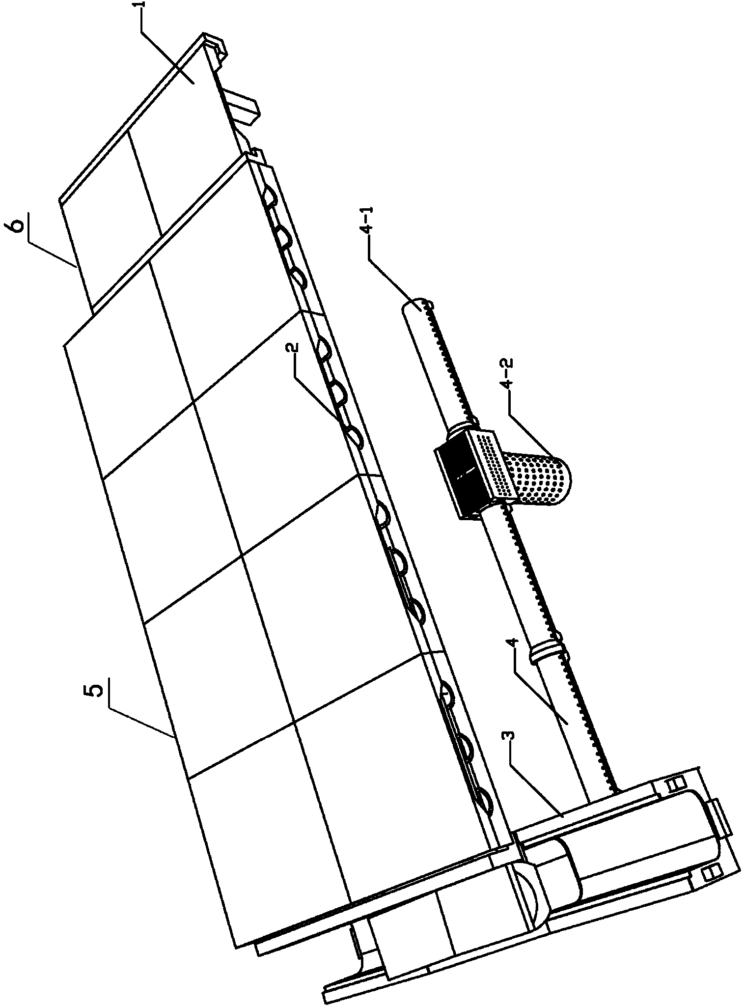
[0079] see figure 1 As shown, the seepage drainage beam-slab pavement composite structure of the preferred first embodiment of the present invention is mainly composed of a beam-slab pavement structure 1, a permeable PC base layer 2, a U-shaped ecological drainage ditch 3 and a seepage drainage pipe 4. Wherein, the beam-slab pavement structure 1 is installed on the permeable PC base layer 2, so that the permeable PC base layer 2 and the beam-slab type pavement structure 1 are combined to form a motorway or a square 5, which has the function of carrying loads. The sidewalks or non-motorized lanes 6 located on one side or both sides of the motorway or the square 5 are assembled from the plurality of beam-slab pavement structures 1 . Sidewalk or non-motorized vehicle lane 6 are provided with the side of motorized lane or square 5 in the present embodiment, see figure 1 . The U-shaped ecological drainage ditch 3 is installed on the sidewalk or the bicycle lane 6 or the side of t...

Embodiment 2

[0091] see Figure 10 As shown, in the preferred second embodiment of the present invention, the seepage drainage beam-slab pavement composite structure, the bottom of the PC pipe 4-12 of the horizontal PC pipe 4-1 is provided with a base 4-13. In the present embodiment, the sidewalk or the non-motorized lane 6 are arranged on both sides of the motorized lane or the square 5, and the U-shaped ecological drainage ditch 3 is arranged on both sides of the sidewalk or the non-motorized lane 6. Other structures are with embodiment 1.

Embodiment 3

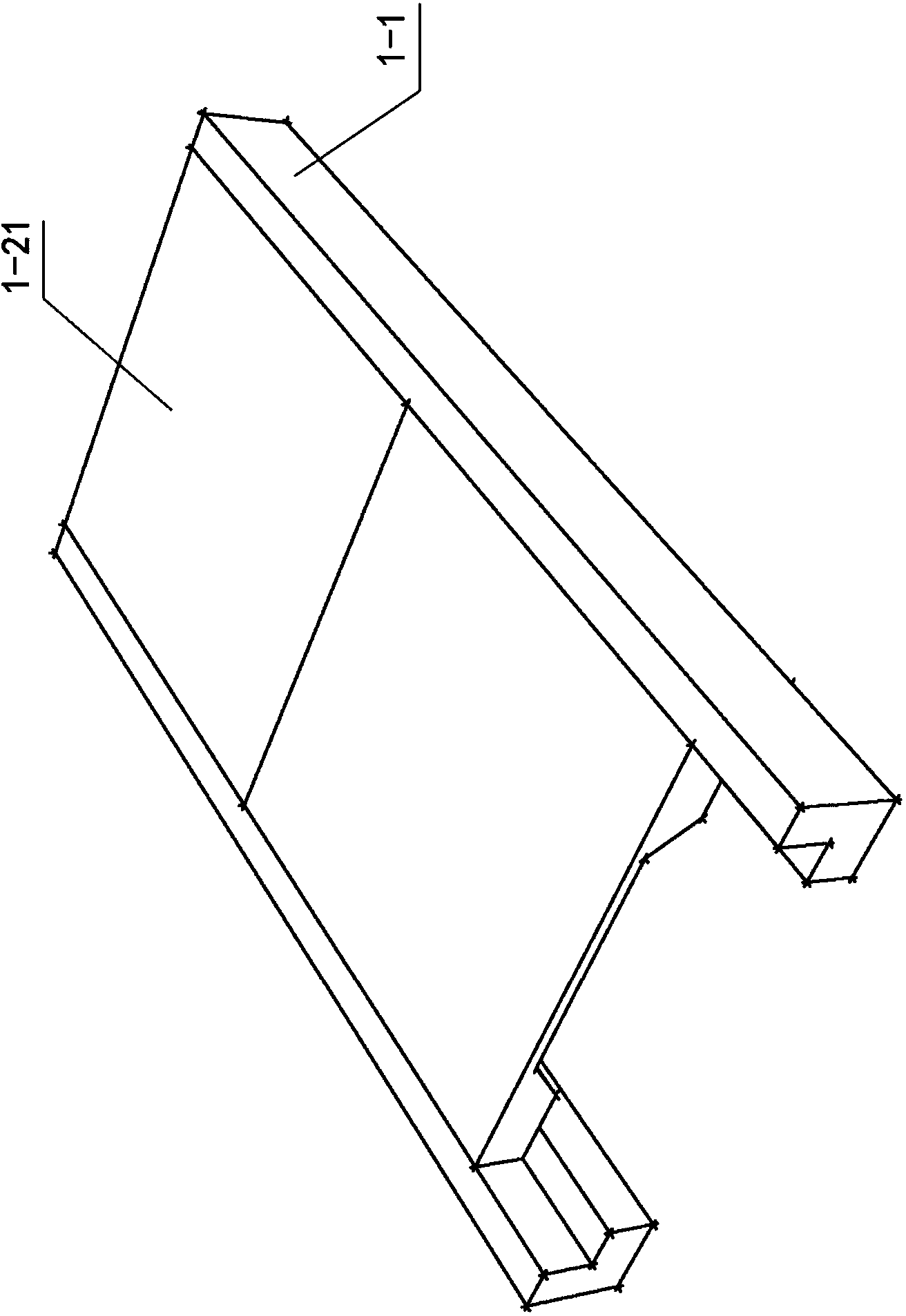
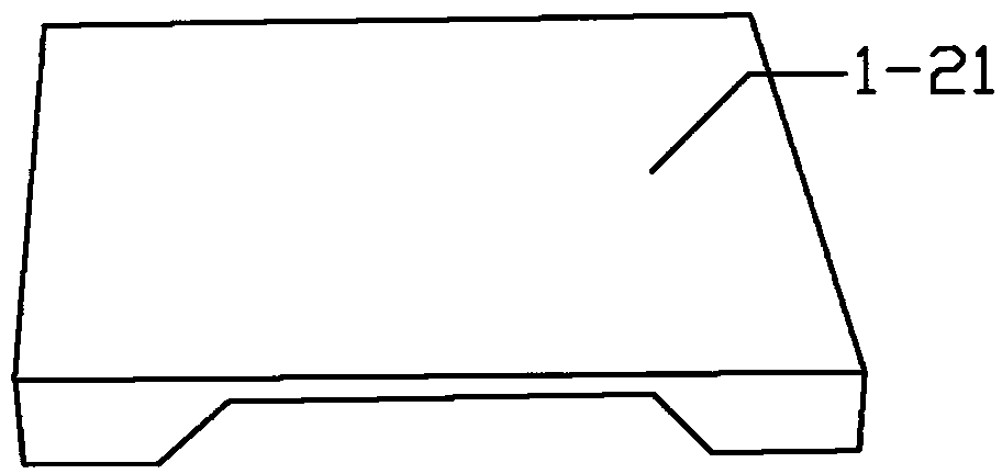
[0093] see Figure 5 , Figure 3A , Figure 3B As shown, in the preferred third embodiment of the present invention, the seepage drainage beam-slab pavement composite structure, the lower bottom of the beam 1-1 is provided with a plurality of columns 1-3, the beam 1-1 is L-shaped, the The right-angled trapezoidal pier 1-23 of the inverted trapezoidal wedge panel 1-2 is arranged at the bottom of the L-shaped beam 1-1. In the present embodiment, the sidewalk or the non-motorized lane 6 is arranged on one side of the motorized lane or the square 5, and the U-shaped ecological drainage ditch 3 is arranged on the side of the sidewalk or the non-motorized lane 6. Other structures are with embodiment 1.

[0094] By using the above embodiments of the invention, the rainwater can be infiltrated into the surface soil of residential areas, office areas, squares, etc. to the maximum extent. When the rainfall is heavy, the rainwater that has no time to infiltrate can be discharged into ...


PUM


Abstract

The invention relates to a drainage and seepage type felting composite structure. The seepage type felting composite structure comprises a beam-slab felting structure, a permeable PC substrate, a U-shaped ecological water draining and collecting ditch, and a seepage and drainage pipe, wherein the beam-slab felting structure is assembled into a side pavement or a motorized vehicle lane; the permeable PC substrate and the beam-slab felting structure are combined into a motor vehicle lane or a square and have a load effect. The U-shaped ecological water draining and collecting ditch is installed at one side or two sides of the motor vehicle lane or the square; the drainage and seepage pipe comprises a transverse PC pipe and a vertical PC pipe; the transverse PC pipe is communicated with the U-shaped ecological water draining and collecting ditch; and the vertical PC pipe is communicated with the transverse PC pipe. The drainage and seepage type felting composite structure is permeable and breathable, can carry out earth surface heat exchange easily, can recycle rainwater effectively, reduces an urban heat island effect, is suitable for eco-environment protection, is simple in structure, and is simple to construct.

Description

technical field [0001] The invention relates to a pavement structure in the field of roads, in particular to a combined pavement structure for drainage of seepage Background technique [0002] The traditional pavement structure of roads and squares is composed of base, surface and cushion, all of which require on-site construction machinery to pave, roll, and lay the base and surface. There are many on-site construction procedures, and the operating procedures of each process are complicated. , the biggest disadvantage is that it is impermeable, airtight, and difficult for surface heat exchange. Since the 1990s, the use of permeable materials to replace traditional materials for pavement has been widely used in urban construction in developed countries. At present, domestic research on material-based permeable pavements focuses on permeable brick pavements and permeable concrete pavements. However, due to cost, There are some difficult bottlenecks in construction technology...

Claims


Application Information

Patent Timeline
Patent Type & Authority Applications(China)
IPC IPC(8): E01C5/00E01C5/20E01C15/00E01C11/00E01C11/22E03F3/02E03F3/04
CPCE01C5/00E01C5/20E01C11/225E01C11/227E01C15/00E03F3/02E03F3/04Y02A30/60
Inventor 祝于华谢浩森
Owner 深圳市致道景观有限公司
Why Eureka
Try Eureka