Small and medium-sized large temperature difference dual-working condition dynamic fluid ice storage air conditioner

An ice-storage air-conditioning and large temperature difference technology, which is applied in air-conditioning systems, space heating and ventilation, heating methods, etc., can solve the problem that air-conditioning pipes cannot be directly used, it is difficult to achieve large temperature difference air-conditioning, and ice is easy to form large ice cubes, etc. problems, to achieve the effect of high-density transportation, high ice-making efficiency and simple structure

Inactive Publication Date: 2017-03-22
王飞波 +1
View PDF4 Cites 0 Cited by
  • Summary
  • Abstract
  • Description
  • Claims
  • Application Information

AI Technical Summary

Problems solved by technology

Increasing the efficiency means that the energy storage density decreases; on the contrary, increasing the ice storage density can increase the efficiency, but it will cause a huge energy storage space
Second, because the stored ice is relatively large and hard, it is difficult to melt the ice quickly when needed.
Although this method has a high ice-making efficiency, the ice produced needs to be frozen in the ice storage tank, and the generated ice is very easy to form large ice cubes, and there is also an inherent weakness of poor ice-melting response
Furthermore, although it is dynamic ice making, its ice formation is static, so it cannot be directly used in air conditioning ducts
It is difficult to achieve large temperature difference air conditioning

Method used


Image

  • Small and medium-sized large temperature difference dual-working condition dynamic fluid ice storage air conditioner
  • Small and medium-sized large temperature difference dual-working condition dynamic fluid ice storage air conditioner

Examples


Embodiment Construction

[0018] Below in conjunction with specific embodiment and accompanying drawing, the present invention is described in detail:

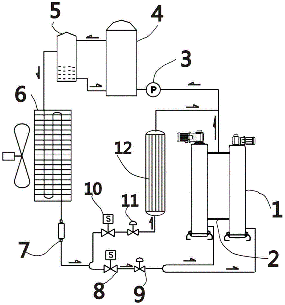
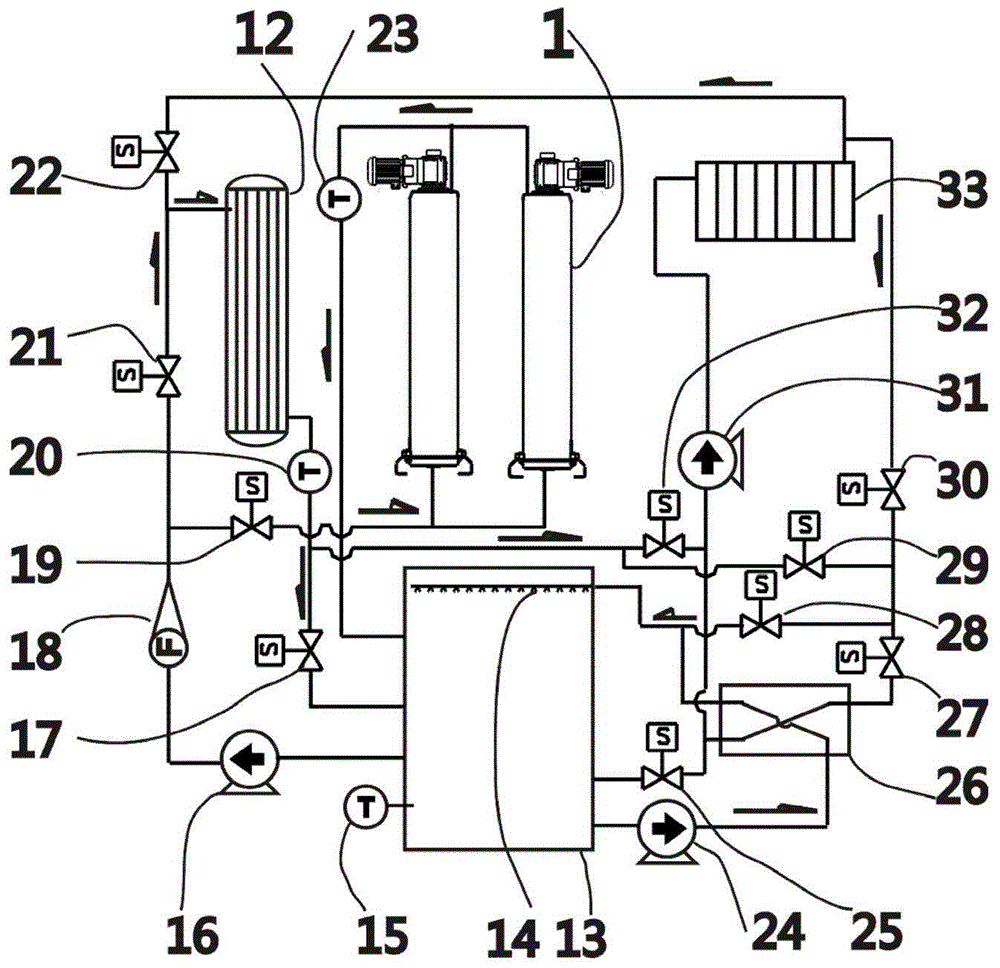
[0019] As shown in the accompanying drawings, the small and medium-sized large temperature difference dual-working condition dynamic fluid ice ice storage air conditioner of the present invention includes a refrigeration cycle device and an air conditioning cycle device, and the refrigeration cycle device includes a water-cooled evaporator 12 and at least one ice crystal device 1. A plurality of ice crystals 1 are connected through the ice crystal refrigerant connection channel 2, and the air conditioning cycle device includes an ice storage tank 13 equipped with a third temperature sensor 15, on the upper part of the ice storage tank A spraying device is installed, and the first water outlet at the bottom of the ice storage tank 13 is connected with the water inlet of the ice-making circulation pump 16, and the water outlet of the ice-making circulatio...


PUM


Abstract

The invention discloses a medium- and small-sized high-temperature-difference double-working-condition dynamic ice-slurry cold storage air conditioner. A refrigerating circulating device comprises a water cooling type evaporator and ice crystal devices, an air conditioning circulating device comprises an ice storage tank, and a water outlet of the bottom end of the ice storage tank is communicated with an ice making circulating pump and a flow meter sequentially; a pipeline of a water outlet of the flow meter is divided into two branches, water outlets of the upper ends of the ice crystal devices are communicated with the ice storage tank via first water outlet pipelines, a water outlet of the water cooling type evaporator is communicated with a water inlet of the ice storage tank via a second water outlet pipeline, one end of an ice melting circulating pipeline is communicated with an inlet of a sprayer, and the other end of the ice melting circulating pipeline is communicated with a second water outlet of the ice storage tank via a secondary heat exchanger. One end of an air-conditioner water inlet pipe is communicated with a third water outlet of the ice storage tank, and the other end of the same is communicated with a water inlet of an air-conditioner tail-end heat exchanger. One end of an air-conditioner water outlet pipe is communicated with a water outlet of the air-conditioner tail-end heat exchanger. The medium- and small-sized high-temperature-difference double-working-condition dynamic ice-slurry cold storage air conditioner can manufacture ice slurry for ice cold storage and can be used as a common air conditioner.

Description

technical field [0001] The invention relates to a new type of dynamic fluid ice storage air conditioner with large temperature difference and dual working conditions, in particular to a latent heat energy storage air conditioning system for producing frozen water and fluid ice, storing and melting ice. Background technique [0002] With the warming of the climate and the improvement of living standards, people's requirements for the summer environment are getting higher and higher, and the use of air conditioners is increasing, especially with the process of urbanization, the amount of air conditioners in large commercial facilities has increased dramatically. In the traditional central air-conditioning system, the chilled water of about 7°C is taken by the refrigeration machine and sent to the air-conditioning terminal equipment to enter the air-conditioning. This method is mature, simple and easy to implement, but this aspect is real-time refrigeration and air conditioning...

Claims


Application Information

Patent Timeline
Patent Type & Authority Patents(China)
IPC IPC(8): F24F5/00
CPCF24F5/0017F24F11/89Y02E60/14
Inventor 王飞波王泽普朱永生潘炳华汪云芳
Owner 王飞波
Why Eureka
Try Eureka