A system and method for monitoring detonation wave velocity changes

A speed change and detonation wave technology, applied in the field of detonation experiments, can solve the problems of limited number of segments and difficult transient speed measurement, and achieve the effects of easy operation, reduced life safety and property hazards, and low cost

Inactive Publication Date: 2016-04-13
EAST CHINA UNIV OF SCI & TECH
View PDF1 Cites 0 Cited by
  • Summary
  • Abstract
  • Description
  • Claims
  • Application Information

AI Technical Summary

Problems solved by technology

At present, the equipment produced at home and abroad uses optical fiber technology to measure the explosion wave velocity of gas explosion or condensed explosives. Because the propagation of gas phase detonation wave has the characteristics of high speed, high temperature, and high energy, and because the number of segments used is limited, it is difficult to measure the velocity of gas phase detonation waves. The transient velocity in the small-scale range of the boom wave is measured

Method used


Image

  • A system and method for monitoring detonation wave velocity changes
  • A system and method for monitoring detonation wave velocity changes
  • A system and method for monitoring detonation wave velocity changes

Examples


Embodiment Construction

[0034] The present invention will be further described in detail below in conjunction with the accompanying drawings.

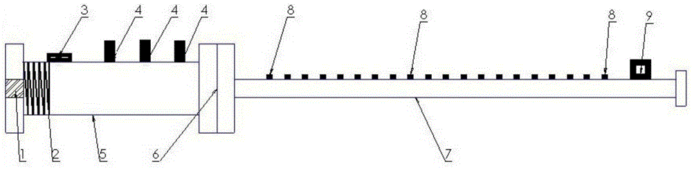
[0035] The system for monitoring the variation of detonation wave velocity of the present invention comprises a detonation tube, such as figure 1 As shown, the detonation tube includes a high-energy ignition head 1 , a drive tube body 5 and a test tube body 7 connected in sequence, and the drive tube body 5 and the test tube body 7 are communicated through a flange 6 . Wherein, the diameter of the driving pipe body 5 is preferably about 60-68 mm, and the length is preferably about 1200-1500 mm. A rigid helical structure 2 is arranged inside one end adjacent to the ignition head 1 to generate turbulence to facilitate the formation of detonation waves, and drive An air inlet 3 is provided on the pipe wall of the pipe body 5 for adding premixed combustible gas; the length of the test pipe body 7 is preferably about 2500-3000 mm, and the pipe diameter is preferab...


PUM

PropertyMeasurementUnit
lengthaaaaaaaaaa
diameteraaaaaaaaaa
lengthaaaaaaaaaa

Abstract

The invention provides a system for monitoring the speed change of detonation waves. The system comprises a detonation pipe, light-guide fiber elements, a photoelectric converting device and an oscilloscope, wherein the detonation pipe comprises a detonating fuse head, a driving pipe body and a test pipe body, the detonating fuse head, the driving pipe body and the test pipe body are connected in sequence, the driving pipe body and the test pipe body are communicated through a flange, a rigid spiral structure is arranged inside the end, near the detonating fuse head, of the driving pipe body, an air inlet is formed in the pipe wall of the driving pipe body, holes are formed in the pipe wall of the driving pipe body every a preset interval, and an air outlet is formed in the pipe wall of the end, away from the flange, of the test pipe; the light-guide fiber elements are fixedly installed on the test pipe body and penetrate through the holes correspondingly to enter the test pipe body, the photoelectric converting device is connected to the light-guide fiber elements, and the optical signals detected by the light-guide fiber elements can be converted into corresponding electric signals; the oscilloscope is connected to the photoelectric converting device and outputs an oscillogram corresponding to the electric signals. The system monitors the speed of the detonation waves in a small-scale range in real time through the multi-channel light-guide fiber elements, and is favorable for judging the volatility of the spreading speed of the detonation waves.

Description

technical field [0001] The invention belongs to the technical field of detonation experiments, and in particular relates to a system and method for monitoring changes in detonation wave velocity. Background technique [0002] Detonation is a phenomenon in which the leading shock wave is strongly coupled to the chemical reaction, and the self-sustained propagation has a strong discontinuity. The propagation speed of detonation wave is generally 2000-3000m / s. Due to the extremely fast movement speed of detonation wave, it is difficult to monitor the speed change of detonation wave in a small scale range (for example, within 100mm), while the fluctuation of detonation wave velocity is The key basis for judging the stability of detonation wave propagation. By measuring the transient velocity of the detonation wave, the risk assessment ability of the detonation hazard of the flammable mixture gas can be improved, so as to effectively avoid or reduce the hazard of detonation to p...

Claims


Application Information

Patent Timeline
Patent Type & Authority Patents(China)
IPC IPC(8): G01N33/00G01N33/22G01H9/00
Inventor 张博沈晓波于文强陈婷陈潇李嘉晨谢禄霖
Owner EAST CHINA UNIV OF SCI & TECH
Why Eureka
Try Eureka