
Voltage transformation type speed measurement device for magnetic liquid

A technology of magnetic liquid and speed measuring device, which is applied in the direction of devices using fluid, devices using electric/magnetic methods, etc., which can solve problems such as poor long-distance accuracy, poor environmental adaptability of photoelectric sensors, and inaccurate speed measurement results. It achieves the effects of high temperature adaptability, adjustable measurement speed range and wide measurement speed range

Inactive Publication Date: 2015-01-28
JILIN UNIV
View PDF4 Cites 7 Cited by
  • Summary
  • Abstract
  • Description
  • Claims
  • Application Information

AI Technical Summary

Problems solved by technology

However, the Hall effect speed sensor has obvious disadvantages: the maximum temperature it can adapt to is 175°C, the air gap of the sensor is less than 2.5mm, and it is very sensitive to external pressure, so changes in the speed measurement environment are likely to cause inaccurate speed measurement results
However, the photoelectric sensor not only has poor environmental adaptability, but also has poor long-distance accuracy.

Method used


Image

  • Voltage transformation type speed measurement device for magnetic liquid
  • Voltage transformation type speed measurement device for magnetic liquid
  • Voltage transformation type speed measurement device for magnetic liquid

Examples


Embodiment Construction

[0044] Embodiments of the present invention will be further described below in conjunction with the accompanying drawings.

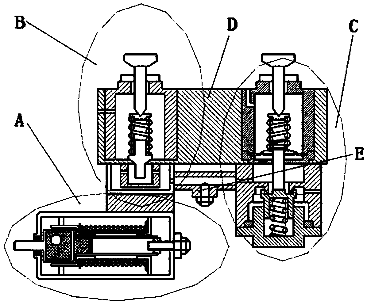
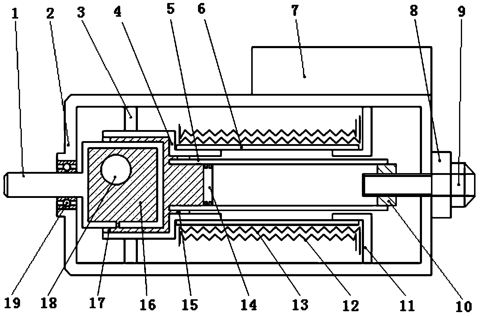
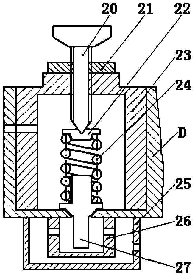
[0045] Refer to attached Figure 1-Figure 9 As shown, the present invention consists of a variable pressure sensing device A, a constant pressure maintaining device B, a pressure control device C, a housing D, a connecting device E and a connecting boss 7, wherein the variable pressure sensor housing of the variable pressure sensing device A 2 The upper right part is affixed to the lower surface of the lower cover 25 of the constant pressure maintaining device B via the connecting boss 7; the outer surface of the valve body I23 of the constant pressure maintaining device B is affixed to the inner surface of the left disc 61 of the housing D, The valve seat I26 of the constant pressure maintaining device B is affixed to the lower surface of the left disc 61 in the housing D, and the lower cover 25 of the constant pressure maintaining device B is affixed t...


PUM


Abstract

The invention provides a voltage transformation type speed measurement device for magnetic liquid, and belongs to the technical field of analyzing and measuring. A voltage transformation sensor shell of a voltage transformation sensing device is fixedly connected with a lower cover of a constant-voltage maintaining device through a connection boss. The valve body outer surface of the constant-voltage maintaining device is fixedly connected with the inner surface of a left circular disc of the shell. A valve base is fixedly connected with the lower surface of the left circular disc in the shell. The lower cover is fixedly connected with the lower surface of the left circular disc in the shell. A hole in the valve body is communicated with a hole in the left circular disc in the shell. A cylinder on the lower portion of the valve core is matched with a conical hole in the left circular disc in the shell in a sliding mode. The conical face of the valve core is matched with the surface of the conical hole in the shell. An upper valve body of a pressure control device, the outer surface of a feed-back valve and the inner surface of a right circular disc of the shell are fixedly connected. The top face of a lower valve body is fixedly connected with the bottom face of the right circular disc of the shell. An opening b of an air guide tee joint of a connection device is communicated with a hole of the lower cover in the pressure maintaining device, and an opening c is communicated with a hole in the lower valve body in the pressure control device. By means of the voltage transformation type speed measurement device, the rotation speeds within different ranges can be measured, and the device is adjustable, high in speed measurement temperature adaptability and stable and accurate in speed measurement.

Description

technical field [0001] The invention belongs to the technical field of analysis and measurement control, and in particular relates to a magnetic liquid pressure variable speed measuring device. Background technique [0002] With the advancement of science and technology, all kinds of power machinery are developing rapidly. Therefore, it is becoming more and more important to know its motion and measure its rotational speed. At present, the most used speed sensors are photoelectric and Hall effect, including crankshaft and camshaft rotation ignition timing control, fuel injection timing control, engine speed measurement, transmission input / output shaft speed detection and electronically controlled shifting. The Hall voltage varies with the strength of the magnetic field. The stronger the magnetic field, the higher the voltage, and the weaker the magnetic field, the lower the voltage. The Hall voltage value is very small, usually only a few millivolts, but the amplifier in t...

Claims


Application Information

Patent Timeline
IPC IPC(8): G01P3/30G01P3/44
Inventor 姚永明胡林强马龙于显利石承钢刘顺安董志岩王春雪
Owner JILIN UNIV
Learn More