
Multi-beam scanning antenna

A scanning antenna, multi-beam technology, applied in the direction of the antenna, electrical components, radiation element structure, etc., can solve the problems of increasing the Rotman lens profile and design difficulty, increasing the number of channels or complexity, etc., to achieve convenient maintenance and antenna structure simple effect

Inactive Publication Date: 2015-01-28
SOUTHEAST UNIV
View PDF6 Cites 11 Cited by
  • Summary
  • Abstract
  • Description
  • Claims
  • Application Information

AI Technical Summary

Problems solved by technology

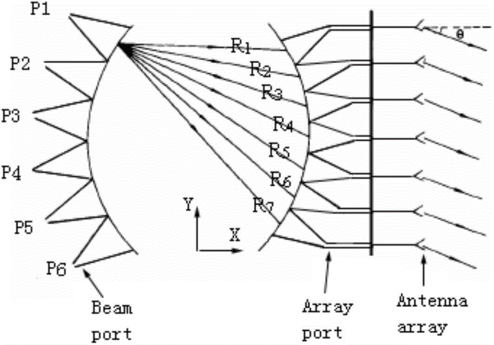
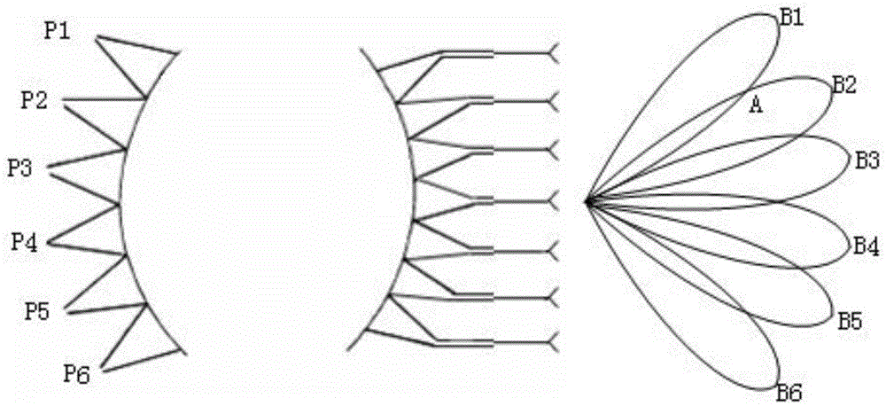
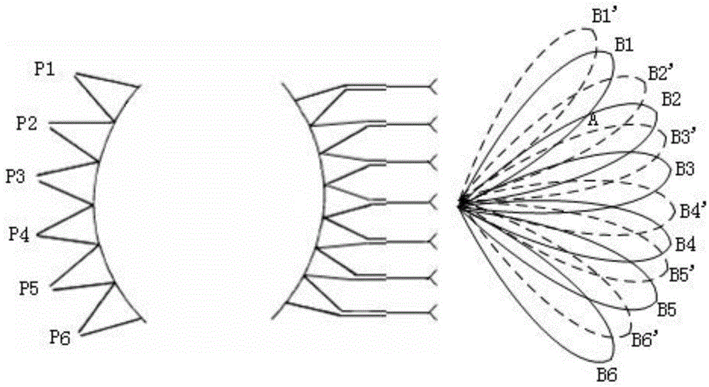
To improve the overall detection capability of the system, the usual method is to increase the number of beam ports, generate more radiation / reception beams, and increase the spatial density of the beams. However, this method not only needs to increase the profile of the Rotman lens and design difficulty , while increasing the number or complexity of channels

Method used


Image

  • Multi-beam scanning antenna
  • Multi-beam scanning antenna
  • Multi-beam scanning antenna

Examples


Embodiment Construction

[0029] Below in conjunction with accompanying drawing, the present invention is further described in detail:

[0030] Such as Figure 4 As shown, the overall structure includes a first PCB board 1, a second PCB board 2, a third PCB board 3 and Figure 5 The coaxial connector shown in 4. Figure 5 In fact, the coaxial connector 4 is installed in the circular through hole 23 of the second PCB board 2 . see Figure 6 , the first PCB board 1 includes a metal ground plate 11 , a substrate and a Rotman lens metal layer pattern 13 , the Rotman lens is connected to the receiver channel through the beam port 131 , and connected to the antenna array through the array port 132 . see Figure 7 , the second PCB board 2 includes a BSTPC substrate, a metal ground plate 22 and a circular through hole 23 . see Figure 8 , the third PCB board 3 includes a BSTPC substrate 31, a microstrip patch array 32, a circular through hole 33 and a DC voltage loading line 34, and the DC voltage loadin...


PUM


Abstract

The invention relates to a multi-beam scanning antenna comprising a first PCB, a second PCB and a third PCB. The three PCBs closely fit one another from bottom to top. A metal grounding plate and a Rotman lens are arranged on a substrate of the first PCB. A micro-strip patch array and a direct-current loading line are arranged on a substrate of the third PCB. One side of the second PCB is provided with through holes in which coaxial connectors are arranged to connect the first PCB and the third PCB. Each of the coaxial connectors includes a metal wire core which is coated with an insulating medium, and both ends of the metal wire core extend out of the insulating medium. The micro-strip patch array is composed of at least two micro-strip patch linear arrays, each micro-strip patch linear array includes at least two micro-strip patch units, and every two micro-strip patch units are connected by a micro-strip line. Compared with the prior art, electric scanning in a two-dimensional space can be realized, and the antenna of the invention is simple in structure and convenient to maintain.

Description

technical field [0001] The invention relates to an antenna system capable of generating multiple receiving (transmitting) beams and realizing two-dimensional scanning of the multiple beams, which can be used to improve the scanning and detection capabilities of large airspace and regional monitoring equipment. Background technique [0002] Multiple Beam Antenna (Multiple Beam Antenna) can cover a large airspace and area with high gain, which makes this antenna have a good application prospect in application systems such as battlefield monitoring and multipoint communication, so it has received extensive attention from various countries. . Phased array radar can realize multi-beam, but in the process of realizing multi-beam, a large number of circuits and other hardware must be added to the already complex phased array radar, which makes the system more complex and more expensive. The Rotman lens is a low-cost, wide-band and easy-to-manufacture multi-beam forming network. An...

Claims


Application Information

Patent Timeline
Patent Type & Authority Applications(China)
IPC IPC(8): H01Q1/38H01Q13/08H01Q3/46
Inventor 王宗新杨非
Owner SOUTHEAST UNIV
Learn More