Arc-shaped micro-strip antenna

A microstrip antenna and arc-shaped technology, which is applied in the field of arc microstrip antennas, can solve the problems of reducing the area of ​​the radiation patch, the limited area of ​​the radiation patch, and the influence of the antenna gain, so as to improve the performance of the antenna, reduce the size of the antenna, and Envelope smooth effect

Inactive Publication Date: 2015-01-28
CHENGDU UNIV OF INFORMATION TECH
View PDF2 Cites 4 Cited by
  • Summary
  • Abstract
  • Description
  • Claims
  • Application Information

AI Technical Summary

Problems solved by technology

However, the slotted structure also has adverse effects on the microstrip antenna, such as reducing the area of ​​the radiation patch, reducing the gain of the antenna, etc.
Especially fo

Method used


Image

  • Arc-shaped micro-strip antenna
  • Arc-shaped micro-strip antenna
  • Arc-shaped micro-strip antenna

Examples


Embodiment 1

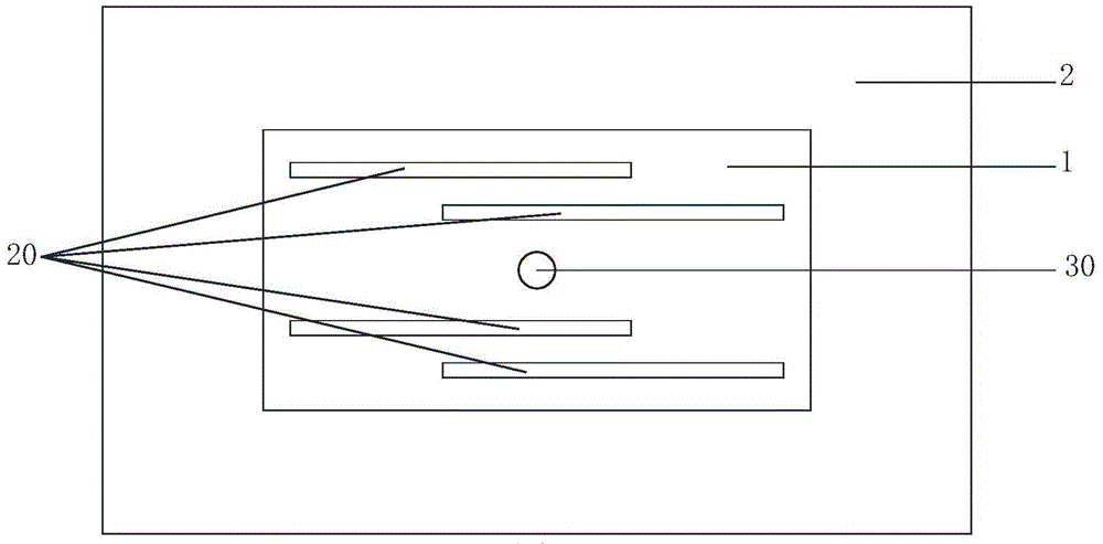
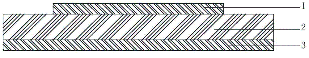
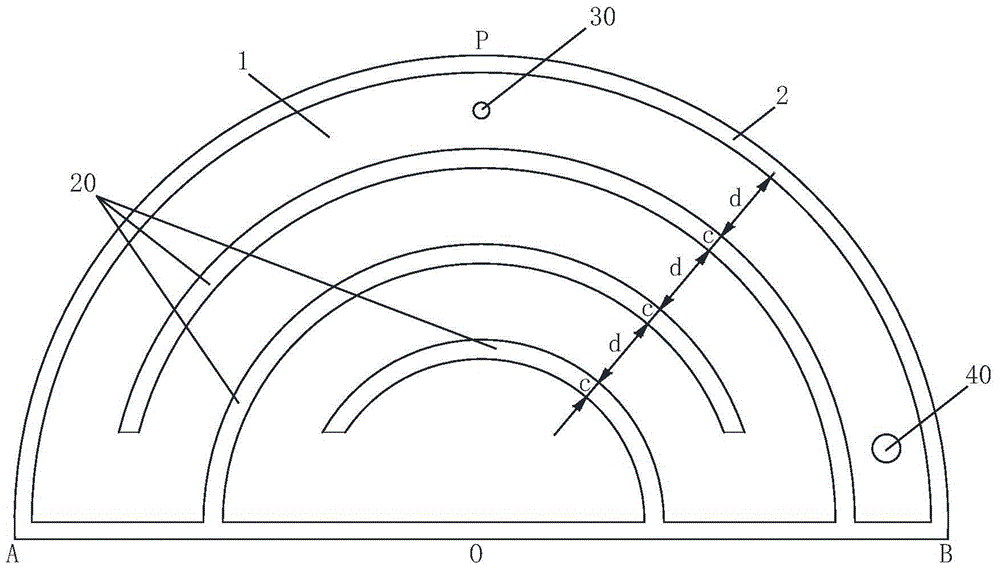
[0040] In this example, the arc-shaped microstrip antenna is a semicircular sheet structure, including a radiation patch 1, a dielectric substrate 2, a ground plane 3 and a dielectric loading layer 4, such as image 3 and Figure 4 shown. The radiation patch 1 is composed of a semicircular metal patch and is arranged on the front of the dielectric substrate 2. The arc side of the radiation patch 1 is a semicircle APB, and the opposite side AOB is the diameter of the semicircle. The area of ​​the dielectric substrate 2 is slightly larger than that of the radiation patch 1 , and a ground plane 3 of the same size is arranged on the back thereof. The ground plane 3 is a metal coating layer, and is connected to the radiation patch 1 through a short circuit 40 . In this example, the radiation patch 1 has a semi-circular arc APB, which is in a convex shape, such as image 3 shown. Three arc-shaped slots 20 of the same width c are arranged at equal intervals d inside the semi-arc ...

Embodiment 2

[0044] Such as Figure 5 As shown, the radiation patch 1 is a shape surrounded by a circular arc APB and a straight line AOB, the circular arc APB is smaller than a semicircular arc, and the area of ​​the radiation patch is smaller than a semicircular radiation patch. For the slotted structure of the antenna, refer to the description of Embodiment 1 .

Embodiment 3

[0046] Such as Figure 6 As shown, the radiation patch 1 is a shape surrounded by a circular arc APB and a straight line AOB, the circular arc APB is larger than the semicircular arc, and the area of ​​the radiation patch is larger than the semicircular radiation patch. For the slotted structure of the antenna, refer to the description of Embodiment 1 .


PUM

PropertyMeasurementUnit
Radiusaaaaaaaaaa
Groove widthaaaaaaaaaa

Abstract

The invention relates to micro-strip antennas and discloses an arc-shaped micro-strip antenna. The arc-shaped micro-strip antenna comprises a radiation patch and a dielectric substrate; the radiation patch is arranged on the front side of the dielectric substrate; at least one edge of the radiation patch is an arc and is in an outward protruding shape; n arc-shaped grooves are separately formed in the inner side of the arc; one end of every arc-shaped groove is connected with the edge of the radiation patch; the beginning end of the first arc-shaped groove is connected with the edge of the radiation patch, the tail end of the second arc-shaped groove is connected with the edge of the radiation patch, the beginning end of the third arc-shaped groove is connected with the edge of the radiation patch, and the like, wherein n is a natural number and n is not less than 1. According to the arc-shaped micro-strip antenna, the large radiation area can be obtained in the limited space; compared with the traditional linear groove structure, the arc-shaped groove structure is long in current path and accordingly the number of grooves can be reduced, the reduction of the size of the antenna is facilitated, and the antenna gain is increased; the arc-shaped micro-strip antenna is particularly suitable for embedding of animals or human bodies.

Description

technical field [0001] The invention relates to a microstrip antenna, in particular to an arc microstrip antenna implanted in animals and human bodies. Background technique [0002] Microstrip antenna structure such as figure 1 and figure 2 As shown, it generally includes a dielectric substrate 2 , a radiation patch 1 attached to the front of the dielectric substrate 2 , and a ground plane 3 on the back of the dielectric substrate 2 . Some microstrip antennas may also not need the ground plane 3 . The dielectric substrate 2 is generally made of an insulating material, and the radiation patch 2 and the ground plane 3 are usually made of a metal patch or a metal coating layer. The radiation patch 2 has different shapes according to different use environments and operating frequencies, and the most common shape of the radiation patch is a circle or a long rectangle. [0003] Microstrip antennas are developing in the direction of miniaturization and broadband. The miniatur...

Claims


Application Information

Patent Timeline
IPC IPC(8): H01Q1/38
Inventor 李荣强
Owner CHENGDU UNIV OF INFORMATION TECH
Why Eureka
Try Eureka