
Ultra-wideband tri-trap antenna

A three-notch, ultra-broadband technology, which is applied in the direction of antenna, antenna grounding device, antenna grounding switch structure connection, etc., can solve the problem of less application and achieve the effect of large number of notches, simple structure and obvious adjustment

Active Publication Date: 2015-01-28
XIDIAN UNIV
View PDF3 Cites 6 Cited by
  • Summary
  • Abstract
  • Description
  • Claims
  • Application Information

AI Technical Summary

Problems solved by technology

However, there are relatively few applications after further optimization of existing theories.

Method used


Image

  • Ultra-wideband tri-trap antenna
  • Ultra-wideband tri-trap antenna
  • Ultra-wideband tri-trap antenna

Examples


Embodiment Construction

[0030] The present invention will be described in further detail below in conjunction with the accompanying drawings.

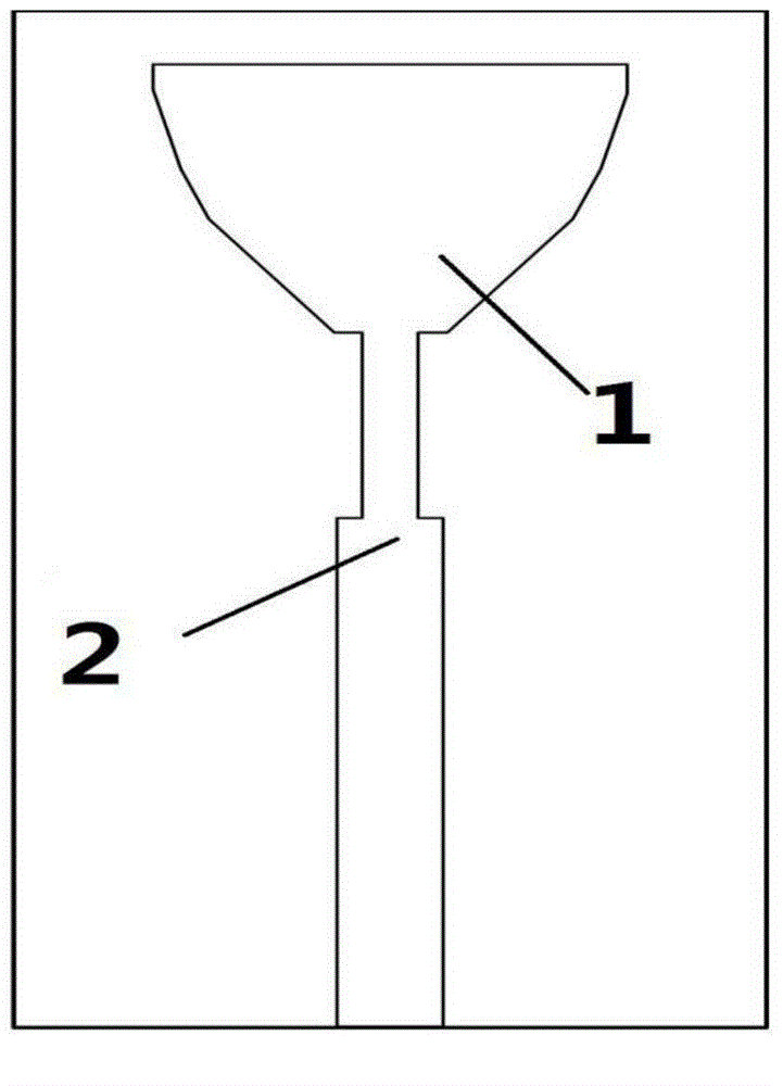
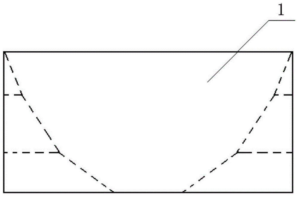
[0031] see figure 1 , the patch antenna of the present invention is printed on a size of 35×17×1.6mm 3 On the FR4 dielectric substrate, the upper and lower surfaces of the dielectric substrate are covered with a radiation patch on the upper surface and a conductive layer on the lower surface, and the material is silver. The radiation patch and the conductive layer are connected through SMA connectors; the radiation unit on the upper surface is a wine glass-shaped patch, and the radiation patch includes the front end 1 of the patch whose aperture decreases from a large gradient and a stepped rectangular microstrip connected to the tail of the front end 1 of the patch. The input impedance of the feeder 2 and the microstrip feeder 2 is 50 ohms, and the front end of the patch 1 is a gradient structure left by cutting the triangular part and the trapezoidal part ...


PUM


Abstract

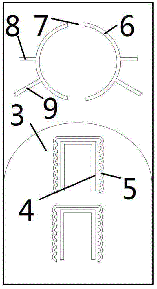
An ultra-wideband tri-trap antenna comprises a dielectric substrate. The upper surface and the lower surface of the dielectric substrate are respectively coated with a radiation patch and a conductive layer. The radiation patch comprises a patch front end in the diameter decreasing and a micro-strip feeder line connected to the tail of the patch front end. The conductive layer comprises a base plate with arc-shape edge and a split ring reflector arranged above the base plate with arc-shape edge. The arc-shaped edge of the base plate with arc-shape edge protrudes upwards. The base plate with arc-shape edge is provided with a U-shaped groove with a downward opening. The split ring reflector comprises an upper ring with a rectangular opening, a lower ring with a rectangular opening and symmetrical branches arranged outside the rings. According to the ultra-wideband tri-trap antenna, straight grooves in both inner side edges of the U-shaped groove and wave grooves outside the U-shaped groove are used for trapping the frequency band of a wireless local area network and the C-band respectively, and the non-base plate area at the bottom of the antenna is used for trapping the downlink band of the X-band through the split ring reflector with double openings and the branches. The ultra-wideband tri-trap antenna has the advantages of being novel in overall structure, small in size, high in trap quantity, good in trap form and the like.

Description

technical field [0001] The invention relates to an ultra-wideband antenna, in particular to an ultra-wideband triple-notch antenna. Background technique [0002] The microstrip antenna has the advantages of small size, simple structure, and easy integration, so the microstrip antenna has a wide range of applications. In recent years, research on ultra-wideband (Ultra-Wideband) antennas has attracted more and more attention, especially after the FCC specified the 3.1-10.6GHz frequency band as a civilian frequency band in 2002, and developed ultra-wideband antennas for this frequency band. Subsequently, there is overlap with some existing frequency bands, such as wireless metropolitan area network (WiMax, 3.3-3.6GHz), C-band satellite communication (3.7-4.2GHz), wireless local area network (WLAN, 5.2-5.8GHz), X Band satellite communication (7.25-7.75GHz, 7.9-8.4GHz), etc., so the practicability of the ultra-wideband notch antenna is very strong. [0003] Ultra-wideband notch...

Claims


Application Information

Patent Timeline
Patent Type & Authority Applications(China)
IPC IPC(8): H01Q1/38H01Q1/48H01Q1/50H01Q15/14H01Q19/10
Inventor 周宇香鄢泽洪樊芳芳王金辉费冬亮范彬彬蒋晓薇
Owner XIDIAN UNIV
Learn More