

Parallel circuit for AC power generator
A technology of alternator and generator, applied in the direction of single-grid parallel feeding arrangement, etc., can solve the problems of complicated circulation control, and achieve the effect of preventing circulation, improving power supply efficiency and simple installation.
- Summary
- Abstract
- Description
- Claims
- Application Information
AI Technical Summary
Problems solved by technology
Method used
Image

Examples
Embodiment Construction
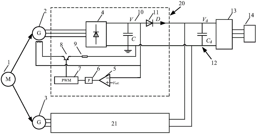
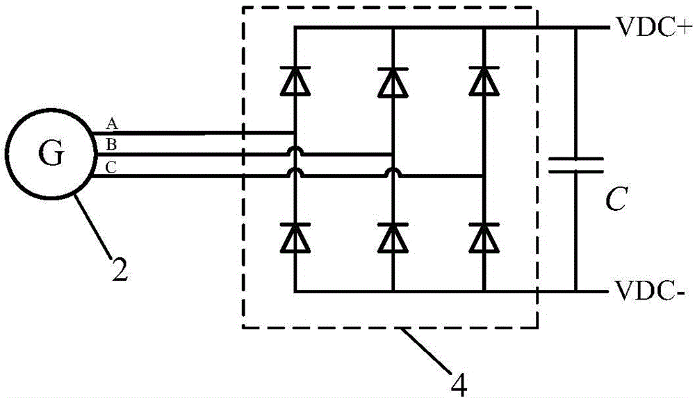
[0014] like figure 1 It is the parallel circuit diagram of the alternator of the present invention, as shown in the figure: including the main generator 2 and the slave generator 3, the parallel control module 20 of the master generator 2 and the parallel control module 21 of the slave generator 3, the DC bus 12 and An inverter bridge 13, the main alternator 2 and the slave alternator 3 are respectively connected to the automobile engine 1 through a power take-off or a belt, and the parallel control module 20 of the main generator 2 includes a diode power module 4 and a comparison unit 5 , proportional link 6, PWM generator 7, IGBT switch tube 8, current limiting resistor 9, capacitor 10 and diode 11; the input end of the diode power module (4) is connected with the three-phase output end of the generator (2), The positive output terminal is connected to the positive terminal of the capacitor C and the anode of the diode 11, and then connected to the positive terminal of the i...
PUM
 Abstract
Description
Claims
Application Information