Wire winding machine for stator core of motor

A motor stator and winding machine technology, which is applied in the field of motor stator core winding machines, can solve problems such as single structure of winding nozzles, low winding efficiency, and inability to realize automation, so as to solve the instability of power grid voltage and improve production Efficiency, beautiful shape effect

Inactive Publication Date: 2015-01-28
CHANGZHOU JINKANG PRECISION MECHANISM
View PDF7 Cites 23 Cited by
  • Summary
  • Abstract
  • Description
  • Claims
  • Application Information

AI Technical Summary

Problems solved by technology

[0005] Although the above-mentioned winding machine can realize the winding work, compared with the traditional winding technology, the degree of automation has been improved, but because the structure of the winding nozzle is very single, the lifting of the main shaft 9 can only be realized on one skeleton each time Winding enameled wire has the defect o

Method used


Image

  • Wire winding machine for stator core of motor
  • Wire winding machine for stator core of motor
  • Wire winding machine for stator core of motor

Examples


Embodiment Construction

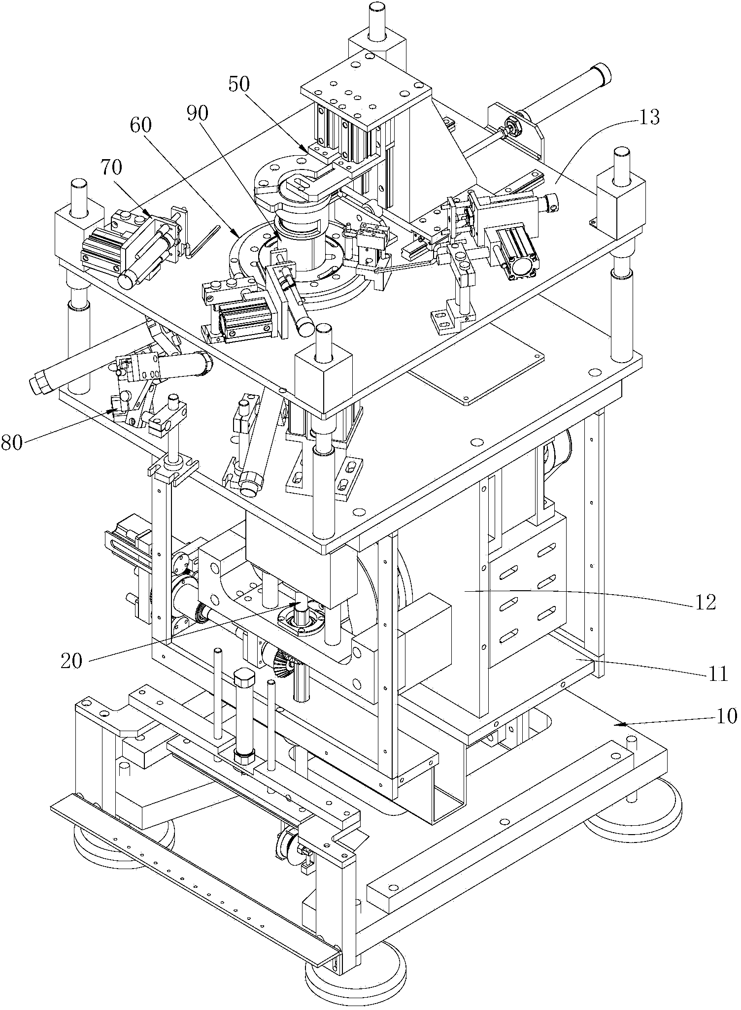
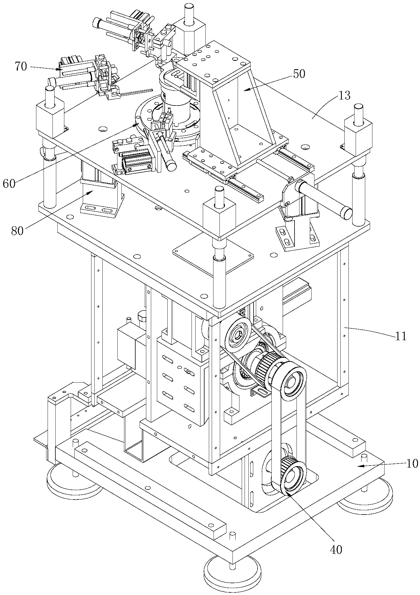
[0093] Such as figure 1 with figure 2 As shown, the motor stator core winding machine of the present invention consists of a frame 10, a wire arrangement 20, a wire winding mold 30, a driving mechanism 40, an axial compression device 50 of the stator core, an indexing mechanism 60, and a pick The thread mechanism 70 and the thread trimming mechanism 80 are composed. The following describes each part and the relationship between them in detail:

[0094] Such as figure 1 with figure 2 As shown, the rack 10 includes a frame frame 11, a mounting plate 12 arranged longitudinally along the frame frame 11, an upper panel 13 arranged horizontally along the frame frame 11 and above the mounting plate 12, the mounting plate 12 and the upper panel 13 are both It is arranged on the frame body 11, the mounting plate 12 is located in the middle of the frame body 11 and is fastened to the frame body 11 by bolts or welding as a whole, and the upper platform panel 13 is provided with a mountin...


PUM


Abstract

The invention relates to a wire winding machine for a stator core of a motor. The wire winding machine for the stator core of the motor comprises a rack, a wire arranging mechanism, a wire winding die and a driving mechanism. The rack comprises a rack frame body, a mounting plate and an upper tabletop plate, wherein the mounting plate is arranged longitudinally along the frame body, and the upper tabletop plate is arranged transversely along the frame body and located above the mounting plate. The wire arranging mechanism is arranged longitudinally along the rack and supported by the mounting plate of the rack and comprises an outer tube and an inner tube which is surrounded by the outer tube partially. The wire winding die is connected with the outer tube and the inner tube of the wire arranging mechanism, and the axial direction of the wire winding die and the axial direction of the mounting hole of the upper tabletop plate are on the same straight line. The driving mechanism is mounted on the rack and connected with the circumferential surface of the outer tube and the circumferential surface of the inner tube. The wire winding machine for the stator core of the motor can enter a shaft hole of the stator core so that an enamelled wire can be wound around a framework of the stator core.

Description

Technical field [0001] The invention relates to the field of motor stator iron cores, in particular to a motor stator iron core winding machine. Background technique [0002] The stator of the motor consists of a stator iron core and a winding wound on the stator iron core, and the wire group adopts enameled wire. Early enameled wire was wound on the stator core by mechanical winding. When the mechanical winding work, the core and wire mold must be assembled manually, and then the whole is installed in the fixture of the winding machine. The wire is wound with copper wire. This method of working iron core assembly method is not only troublesome and time-consuming, and reduces production efficiency, but also the operator needs to reach into the fixture to take out the iron core every time the iron core is wound, and frequently reach into the fixture, winder and other parts of the work. In the Taiwan area, potential safety hazards are highlighted. [0003] As the manufacturing tec...

Claims


Application Information

Patent Timeline
IPC IPC(8): H02K15/085
Inventor 钟仁康彭庆华杨烨
Owner CHANGZHOU JINKANG PRECISION MECHANISM
Why Eureka
Try Eureka