Eureka AIR delivers breakthrough ideas for toughest innovation challenges, trusted by R&D personnel around the world.

Air door device provided with turning plate for power station and blocking method

A damper device, flap door technology, applied in the combustion method, valve configuration, exhaust gas device and other directions, to achieve the effect of easy maintenance, easy operation, and good isolation of the medium

Inactive Publication Date: 2015-02-04
HEILONGJIANG HONGYU POWER STATION EQUIP
View PDF0 Cites 7 Cited by
  • Summary
  • Abstract
  • Description
  • Claims
  • Application Information

AI Technical Summary

Problems solved by technology

[0002]The traditional air door does not have the function of louvers and flap doors, and there is no sealing device, so it cannot achieve the function of blocking the medium, pollutes the environment, is inconvenient to operate, and the structure unreasonable

Method used


Image

  • Air door device provided with turning plate for power station and blocking method
  • Air door device provided with turning plate for power station and blocking method

Examples


Embodiment 1

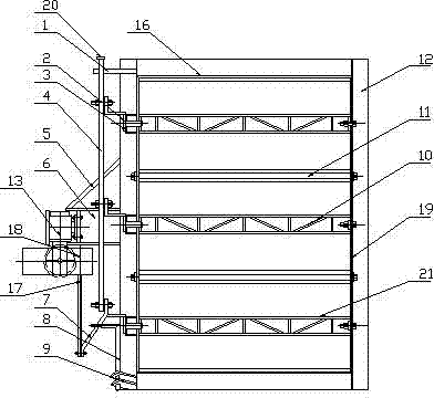
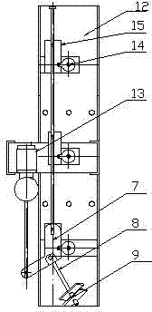
[0021] A flap damper device for a power station, its composition includes: the flap door 10 is connected with a door frame 12, the door frame is connected with a bearing seat 3, the bearing seat is connected with a ratchet shaft 2, the The ratchet shaft is connected with the connecting rod shaft connecting plate 15, the connecting rod shaft connecting plate is connected with the connecting rod shaft 4, the connecting rod shaft connecting plate is connected with the hinge shaft 8, and the hinge shaft and the hinge shaft are installed Plate 9 is connected, the hinge shaft mounting plate is connected with the door frame, the connecting rod shaft connecting plate is connected with the cylinder piston 17, the cylinder piston is connected with the air pump 18, and the air pump is connected with the motor 13 , the door frame is connected with a set of partitions 11 .

Embodiment 2

[0023] According to the flap damper device for the power station described in Embodiment 1, there is a sealing strip 16 inside the door frame, reinforcing ribs 19 are installed on both sides of the door frame, and the partition is connected to the door frame The sealing strip is installed at the place, the locking piece is arranged on the connecting rod shaft, the connecting rod shaft is connected with the connecting rod shaft guide block, and the connecting rod shaft guide block is connected with the door frame.

Embodiment 3

[0025] According to the flap damper device for a power station described in embodiment 1 or 2, there are bearings in the bearing seat, the partition plate is made of stainless steel, and the edge is grooved with a sealing strip, and the air pump There is a hand wheel on the top, the motor is connected with the motor base, the motor base is connected with the door frame, and the motor base has reinforcing ribs.


PUM


Abstract

The invention discloses an air door device provided with a turning plate for a power station and a blocking method. The conventional air door does not have the function of a shutter or a turning plate door, and a sealing device is not provided for blocking media, thereby leading to environmental pollution, inconvenience in operation and unreasonable structure. The air door device provided with the turning plate for the power station is characterized in that a turning plate door (10) is connected with a door frame (12); the door frame is connected with a bearing seat (3); the bearing seat is connected with a ratchet shaft (2); the ratchet shaft is connected with a connecting rod shaft connecting plate (15); the connecting rod shaft connecting plate is connected with a connecting rod shaft (4); the connecting rod shaft connecting plate is connected with a hinge shaft (8); the hinge shaft is connected with a hinge shaft mounting plate (9); the hinge shaft mounting plate is connected with the door frame; the connecting rod shaft connecting plate is connected with a cylinder piston (17); the cylinder piston is connected with an air pump (18); the air pump is connected with a motor (13); the door frame is connected with a group of clapboards (11). The air door device is applied to a dust-removing system of flue gas and a partition of cold and hot air.

Description

Technical field: [0001] The invention relates to a damper device with a flap for a power station and a blocking method. Background technique: [0002] The traditional air door does not have the function of louver and flap door, and has no sealing device, so it cannot achieve the function of blocking the medium, pollutes the environment, is inconvenient to operate, and has an unreasonable structure. Invention content: [0003] The object of the present invention is to provide a damper device with a flap and a blocking method for a power station. [0004] Above-mentioned purpose realizes by following technical scheme: [0005] A flap damper device for a power station, comprising: a flap door, the flap door is connected to a door frame, the door frame is connected to a bearing seat, the bearing seat is connected to a ratchet shaft, the The ratchet shaft is connected to the connecting rod shaft connecting plate, the connecting rod shaft connecting plate is connected to t...

Claims


Application Information

Patent Timeline
Patent Type & Authority Applications(China)
IPC IPC(8): F23L13/00F23J13/08
Inventor 于占军
Owner HEILONGJIANG HONGYU POWER STATION EQUIP
Why Eureka
Eureka Blog
Learn More