Anti-blocking and cooling device for flue gas inlet of deacidification tower and its use method

A flue gas inlet and cooling device technology, which is applied in separation methods, chemical instruments and methods, and the use of liquid separation agents, can solve problems such as high labor intensity, poor operating environment, and increased sewage volume in the deacidification system

Active Publication Date: 2021-05-11
XINZHONGTIAN ENVIRONMENTAL PROTECTION
View PDF8 Cites 0 Cited by
  • Summary
  • Abstract
  • Description
  • Claims
  • Application Information

AI Technical Summary

Problems solved by technology

[0002] The incineration flue gas of thermal power generation, domestic waste incineration, hazardous waste incineration, etc. contains high concentration of acidic substances (mainly SO2, HCl). The deacidification process is used to remove acidic substances. Because a large amount of acidic substances in the flue gas react quickly with the absorbent to form salt at high temperature, the circulating fluid is in direct contact with the high-temperature flue gas, and the water evaporates quickly to cause salt crystallization. The deposition at the entrance of the deacidification tower causes blockage, and the flue gas contains a large amount of fine dust, which is mixed with crystallized salt to form a high-hardness substance like "stalactite", which further aggravates the The current solution is to set a certain number of manholes on the flue at the entrance of the tower, and regularly remove the blockages manually. The operating environment is poor and the labor intensity is high; To avoid blockage of the inlet flue, industrial water is used for spraying to reduce the temperature of the flue gas to below 160°C, which causes waste of industrial water and increases the amount of sewage in the deacidification system

Method used


Image

  • Anti-blocking and cooling device for flue gas inlet of deacidification tower and its use method
  • Anti-blocking and cooling device for flue gas inlet of deacidification tower and its use method
  • Anti-blocking and cooling device for flue gas inlet of deacidification tower and its use method

Examples


Embodiment Construction

[0019] The present invention will be further described below in conjunction with accompanying drawing.

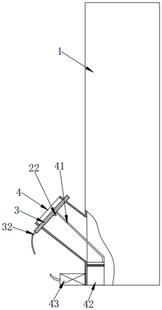
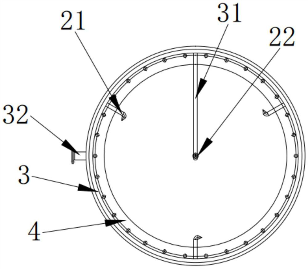
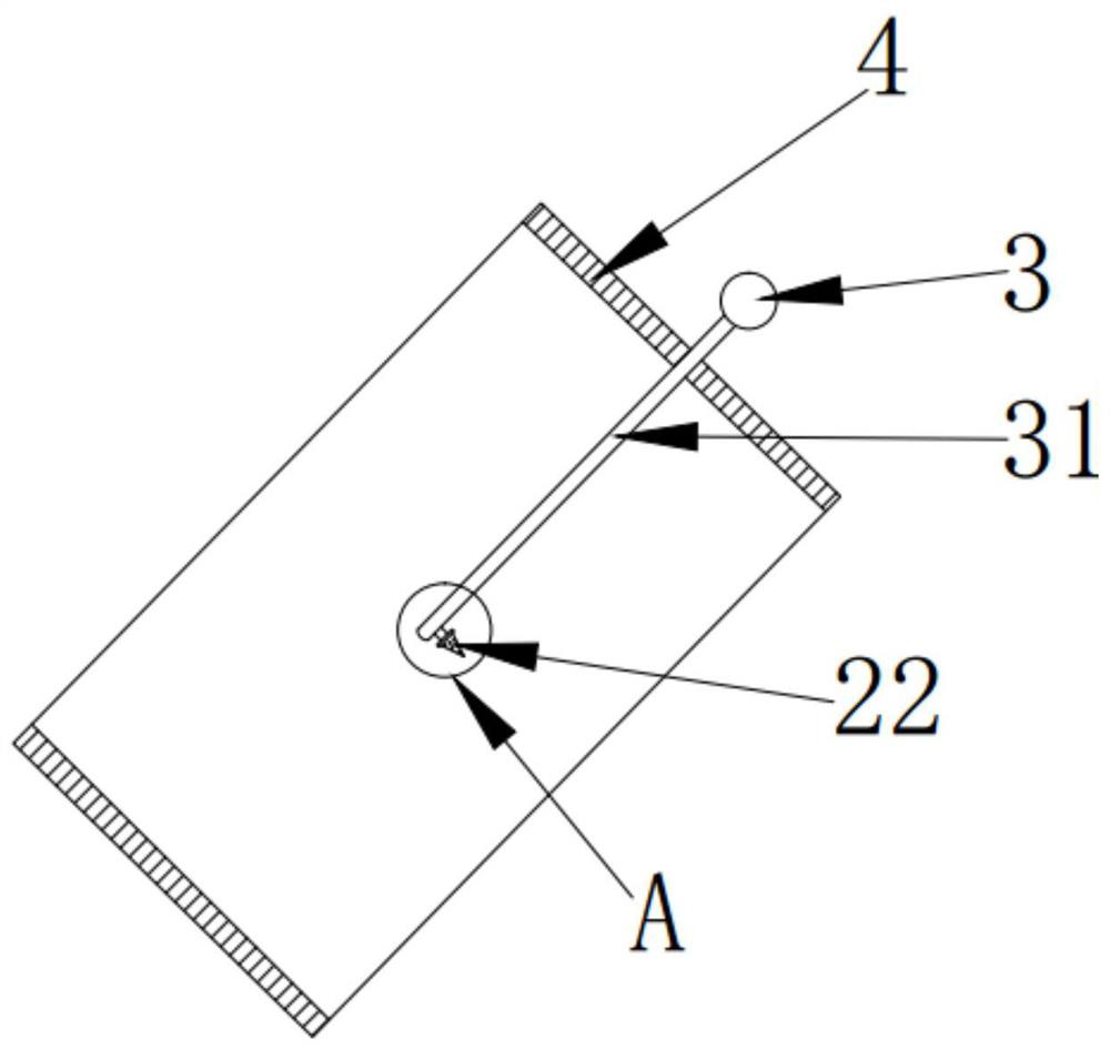
[0020] Depend on figure 1 , figure 2 , image 3 , Figure 4 and Figure 5 As shown, the present invention is composed of a deacidification tower body 1 and an air inlet 4. At the air inlet 4, three fixed through holes are uniformly wound around the side wall of the inlet position. First nozzles 21 are perforated in the holes, one end of each first nozzle 21 extends into the corresponding position of the air inlet 4, and the other end extends outwards from the corresponding position of the air inlet 4, and is connected with the annular The water pipe 3 is in screw connection, and the axial centerline of the annular water pipe 3 is on the same straight line as the axial centerline of the air inlet 4 . One end of the first nozzle 21 extending into the air inlet 4 is a wedge-shaped structure with a rectangular cross section. The axial centerline of the wedge-shaped struct...


PUM


Abstract

The invention discloses a deacidification tower flue gas inlet anti-blocking and cooling device, which comprises a deacidification tower body (1) and an air inlet (4), and a first nozzle (21) is arranged at the air inlet (4). ), the first nozzle is communicated with the annular water pipe (3), and the annular water pipe (3) is also communicated with a connecting pipe (31), and the connecting pipe (31) is provided with a second nozzle (22); A detachable recovery device is provided on the connecting pipe (31), and a water inlet (32) is provided on the annular water pipe (3). The invention also discloses a method for using the anti-blocking cooling device for flue gas inlet of the deacidification tower. The above-mentioned device and method of use can isolate the high-temperature flue gas from the flue, take away the settled foreign matter in the flue gas in time, avoid the formation of "stalactite"-like blockages on the flue, and reduce the Damage to flue material due to wet and high acid corrosion.

Description

technical field [0001] The invention relates to an anti-blocking and cooling device for flue gas inlet of a deacidification tower. The invention also relates to a method for cooling and preventing blockage of the deacidification flue gas. Background technique [0002] The incineration flue gas of thermal power generation, domestic waste incineration, hazardous waste incineration, etc. contains high concentration of acidic substances (mainly SO2, HCl). The deacidification process is used to remove acidic substances. Because a large amount of acidic substances in the flue gas react quickly with the absorbent to form salt at high temperature, the circulating fluid is in direct contact with the high-temperature flue gas, and the water evaporates quickly to cause salt crystallization. The deposition at the entrance of the deacidification tower causes blockage, and the flue gas contains a large amount of fine dust, which is mixed with crystallized salt to form a high-hardness sub...

Claims


Application Information

Patent Timeline
Patent Type & Authority Patents(China)
IPC IPC(8): B01D53/78B01D53/40B01D53/96B01D47/06
CPCB01D47/06B01D53/40B01D53/78B01D53/96B01D2251/304B01D2251/604B01D2258/0283
Inventor 左姣林辉荣毛小英何睿鸣汪小飞刘泉阳杨
Owner XINZHONGTIAN ENVIRONMENTAL PROTECTION
Why Eureka
Try Eureka