Photoelectric composite cable laid in seabed, and manufacture method thereof

A technology for optoelectronic composite cables and optical fibers, which is used in submarine cables, cable/conductor manufacturing, power cables including optical transmission components, etc., to achieve compact structure, transportation cost savings, and small outer diameter.

Active Publication Date: 2015-02-04
NINGBO RONGHE WIRE CO LTD
View PDF8 Cites 17 Cited by
  • Summary
  • Abstract
  • Description
  • Claims
  • Application Information

AI Technical Summary

Problems solved by technology

[0004] The publication number is CN102290135A, the name is: rated voltage 220kV three-core photoelectric composite submarine cable, including the outer covering layer, armor layer and inner Lining layer, the inner lining layer is provided with three two-phase circumscribed electrical units, and the three gaps surrounded by the electrical unit and the inner lining layer are filled with a plurality of filling units, The three electrical units and all the filling units are all stranded to form a main core part of the submarine cable, and the main core part of the stranded submarine cable is wrapped with a rubberized tape, and at least one of all the filling units is The light unit, and the rest of the filling units are filling ropes; there is the same defect as the patent with the authorized notification number CN2817011

Method used


Image

  • Photoelectric composite cable laid in seabed, and manufacture method thereof
  • Photoelectric composite cable laid in seabed, and manufacture method thereof
  • Photoelectric composite cable laid in seabed, and manufacture method thereof

Examples


Embodiment 1

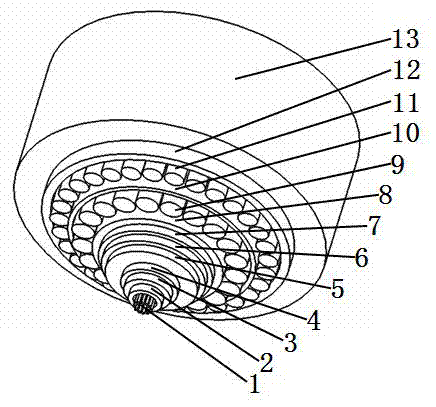
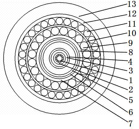
[0029] please see figure 1 and figure 2 , a photoelectric composite cable for submarine laying, is characterized in that it includes 12 optical fibers 1, a loose tube 2 covering the optical fiber, a heat insulation layer 3 wrapped outside the loose tube, and distributed outside the heat insulation layer The conductor layer 4, the insulating layer 5 located outside the conductor layer, the shielding layer 6 located outside the insulating layer, the first protective layer 7 wrapped outside the shielding layer, the inner layer wrapped outside the first protective layer by extrusion Sheath 8, the first armor layer positioned outside the inner sheath, the second protective layer 10 coated outside the first armor layer, the second armor layer positioned outside the second protective layer, extruded plastic wrap The third protective layer 12 covered outside the second armor layer, the outer sheath 13 coated by extrusion molding outside the third protective layer; the first armor la...

Embodiment 2

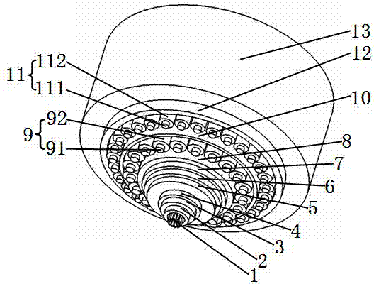
[0032] please see image 3 and Figure 4, a photoelectric composite cable for submarine laying, is characterized in that it includes 12 optical fibers 1, a loose tube 2 covering the optical fiber, a heat insulation layer 3 wrapped outside the loose tube, and distributed outside the heat insulation layer The conductor layer 4, the insulating layer 5 located outside the conductor layer, the shielding layer 6 located outside the insulating layer, the first protective layer 7 wrapped outside the shielding layer, the inner layer wrapped outside the first protective layer by extrusion Sheath 8, the first armor layer positioned outside the inner sheath, the second protective layer 10 coated outside the first armor layer, the second armor layer positioned outside the second protective layer, extruded plastic wrap The third protective layer 12 covered outside the second armor layer, the outer sheath 13 coated by extrusion molding outside the third protective layer; the first armor lay...


PUM

PropertyMeasurementUnit
diameteraaaaaaaaaa

Abstract

The invention belongs to the technical field of a cable, and relates to a photoelectric composite cable laid in a seabed. The cable comprises multiple fibers, a loose sleeve, a thermal insulation layer, a conductor layer, an insulation layer, a shielding layer, a first protective layer, an inner sheath, a first armored layer, a second protective layer, a second armored layer, a third protective layer and an outer jacket. The first armored layer is formed by spirally twisting first reinforcement elements around the inner sheath in a unidirectional mode by a first pitch; the second armored layer is formed by spirally twisting second reinforcement elements around the second protective layer in a unidirectional mode by a second pitch; the winding directions of the first pitch and the second pitch are opposite; the second pitch is 3 to 5 times the first pitch; the ratio of the first pitch to the external diameter of the inner sheath equals to (3-6):1; the materials of the first reinforcement elements are steel wires or alloy wires; and the materials of the second reinforcement elements are the steel wires or the alloy wires. The cable provided by the invention has the following advantages: the cable can transmit both optical signals and electric power, can also resist bending and torsion, and is more compact in structure, longer in life, smaller in external diameter, lower in cost and lower in transport cost.

Description

technical field [0001] The invention belongs to the technical field of submarine cables, in particular to a photoelectric composite cable for submarine laying and a manufacturing method thereof. Background technique [0002] Submarine power transmission and communication signal transmission are solved by two cables, that is, the submarine power cable for power transmission and the submarine optical cable for communication signal transmission, which are laid independently on the seabed. In addition, the cables and optical cables must have the properties of anti-seepage, high water pressure resistance, tensile strength, anti-corrosion, anti-wear, etc., so as to meet the requirements for use on the seabed. Therefore, although existing submarine cable and optical cable have solved the problem of electric power and communication signal transmission, manufacturing cost and laying cost are very high. [0003] For this reason, a large amount of studies have been carried out at hom...

Claims


Application Information

Patent Timeline
Patent Type & Authority Applications(China)
IPC IPC(8): H01B7/17H01B7/04H01B11/22H01B7/14H01B7/18H01B13/00H01B13/24H01B13/14
CPCH01B7/14H01B7/1875H01B7/22H01B7/226H01B9/005H01B9/02H01B9/023H01B13/00H01B13/24H01B13/2613
Inventor 沈群华
Owner NINGBO RONGHE WIRE CO LTD
Why Eureka
Try Eureka