Ultrasound probe

An ultrasonic and acoustic impedance technology, applied in the field of ultrasonic probes, can solve problems such as complex wiring structures

Active Publication Date: 2015-02-11
KONICA MINOLTA INC
View PDF11 Cites 15 Cited by
  • Summary
  • Abstract
  • Description
  • Claims
  • Application Information

AI Technical Summary

Problems solved by technology

Therefore, in the 1.25D to 1.75D array ultrasonic probe, the wiring structure for electrically connecting the electrodes becomes more complicated.

Method used


Image

  • Ultrasound probe
  • Ultrasound probe
  • Ultrasound probe

Examples


no. 1 approach

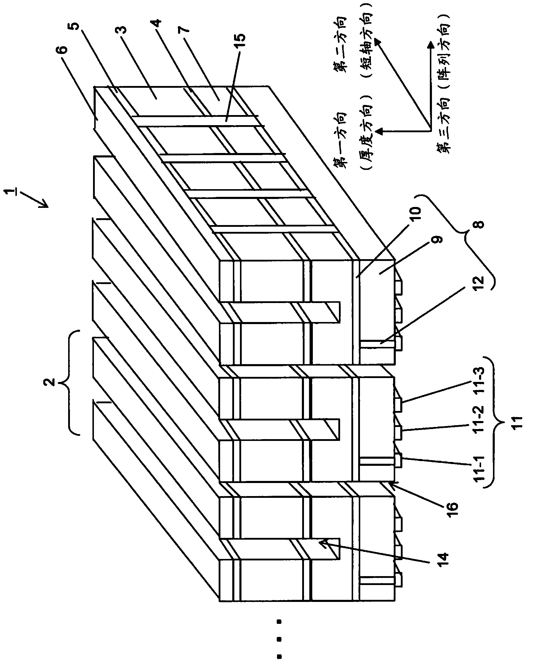
[0053] figure 1 It is a perspective view showing the ultrasonic probe according to the first embodiment of the present invention. figure 1 The ultrasonic probe 1 shown is used in contact with a subject such as a living body. The ultrasonic probe 1 applies an electric signal to the piezoelectric body 3 in the ultrasonic probe 1 to irradiate the subject with ultrasonic waves. A transducer that converts reflected ultrasonic waves from the subject into electrical signals. Such as figure 1 As shown, the ultrasonic probe 1 has: a piezoelectric body 3, a second electrode 4, a first electrode 5, a ground layer 6, an intermediate layer 7, a double-sided FPC 8, a third electrode 11, a first groove 14, and a second groove 15. The third groove 16, the back surface component (not shown), multiple integration layers (not shown) and the lens (not shown).

[0054] If an ultrasonic diagnostic device or an ultrasonic probe is applied between the first electrode (ground electrode) 5 and th...

no. 2 approach

[0121] Figure 23 It is a perspective view showing an ultrasonic probe according to a second embodiment of the present invention. The ultrasonic probe 111 of the second embodiment has a single-sided FPC 13 instead of the double-sided FPC 8 of the ultrasonic probe 1 of the first embodiment. Other than that, the second embodiment is the same as the first embodiment, in that Figure 23 in, right with figure 1 The same structural components are marked with the same symbols.

[0122] Single-sided FPC 13 has third electrode 11 and insulating layer 9 extending in the second direction (short axis direction). As the insulating layer 9, a polyimide film, a polyester film, or the like can be used. Like the double-sided FPC 8 , the single-sided FPC 13 is commercially available in which the third electrode 11 and the insulating layer 9 are pre-stacked, so it is the easiest to use.

[0123] On a part of the third electrode 11 of the single-sided FPC13, in the second direction (minor a...

no. 3 approach

[0133] Figure 31 It is a perspective view showing an ultrasonic probe according to a third embodiment of the present invention. In the ultrasonic probe 111 of the second embodiment, the insulating layer 19 is provided on a part of the third electrode 11, but in this embodiment, as Figure 31 As shown, an insulating layer 29 is provided on the intermediate layer 7 in the second direction (short axis direction). Other than that, the third embodiment is the same as the second embodiment, in Figure 31 in, right with Figure 23 The same structural components are marked with the same symbols.

[0134] When the intermediate layer 7 is formed of a metal material such as aluminum, the insulating layer 29 is formed by selectively performing an alumite treatment. Also, in the case where the intermediate layer 7 is formed of an insulating material, as Figure 6 and Figure 7 As shown, by selectively forming a conductive layer, the portion of the intermediate layer 7 where no condu...


PUM


Abstract

An ultrasound probe includes a laminated body having: a piezoelectric body having a thickness in a first direction; a first electrode and a second electrode that face each other so as to sandwich the piezoelectric body in the first direction; an intermediate layer that is electrically connected with the second electrode and that is provided on an opposite side to the piezoelectric body with respect to the second electrode; and a third electrode that extends in a second direction that is orthogonal to the first direction. A plurality of the first electrodes and second electrodes are arranged at predetermined intervals in the second direction. A plurality of the laminated bodies are arranged in a third direction. A first groove that penetrates through the first electrode, the piezoelectric body, and the second electrode and a part of the intermediate layer is formed in the laminated body.

Description

technical field [0001] The present invention relates to an ultrasonic probe used in an ultrasonic image diagnostic apparatus that radiates ultrasonic waves into a living body and images tissue information in the living body using the ultrasonic waves reflected from each living body tissue. Background technique [0002] Ultrasonic image diagnosis is an image diagnosis method in which ultrasonic waves are irradiated in a living body, and tissue information in a living body is visualized by using the ultrasonic waves reflected from each living body tissue. The piezoelectric body in the ultrasonic probe has the function of generating ultrasonic waves from applied electrical signals, and receiving the ultrasonic waves reflected from tissues in the living body and converting them into electrical signals. [0003] Figure 39 It is a perspective view showing mutual electrical connection of piezoelectric bodies in the 1.5D ultrasonic transducer array shown in Patent Document 1. exis...

Claims


Application Information

Patent Timeline
Patent Type & Authority Applications(China)
IPC IPC(8): A61B8/00
CPCA61B8/4483A61B8/4444B06B1/064A61B8/4494B06B1/0622
Inventor 小泽仁
Owner KONICA MINOLTA INC
Why Eureka
Try Eureka