Flow characteristic correction method for steam turbine high pressure control valve of thermal power generating unit

A technology of high-voltage valve control and thermal power units, which is applied in the direction of machines/engines, mechanical equipment, engine components, etc., to achieve good real-time performance, reduce labor intensity, and facilitate engineering realization

Active Publication Date: 2015-02-11
STATE GRID CORP OF CHINA +2
View PDF11 Cites 25 Cited by
  • Summary
  • Abstract
  • Description
  • Claims
  • Application Information

AI Technical Summary

Problems solved by technology

[0006] Aiming at the problems existing in the above-mentioned prior art, the present invention provides a method for correcting the flow characteristics of the high-pressure valve of the steam turbine of the thermal power unit, the purpose of which is to solve the problem that the thermal power unit participates in The problem of automatic control of the steam turbine high-pressure valve in the process of power grid frequency regulation and peak regulation, to ensure the linear correspondence between the opening of the steam turbine high-pressure valve and the main steam flow when the unit is in frequency regulation and peak regulation

Method used


Image

  • Flow characteristic correction method for steam turbine high pressure control valve of thermal power generating unit
  • Flow characteristic correction method for steam turbine high pressure control valve of thermal power generating unit

Examples


Embodiment Construction

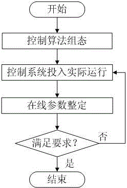
[0026] The present invention is a method for correcting the flow characteristics of a thermal power unit steam turbine with a high pressure valve, such as figure 2 Shown, work flow of the present invention comprises the steps:

[0027] Step 1: Add the steam turbine high-pressure valve flow characteristic correction control loop interface in the logic configuration comprehensive valve position control loop of the original steam turbine digital electro-hydraulic control system;

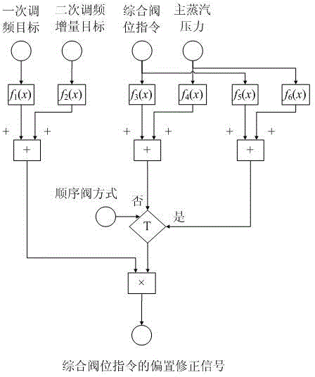
[0028] Step 2: Carry out the logic configuration of the high-pressure regulating door flow characteristic correction control loop of the steam turbine of the thermal power unit, and introduce its output into the flow characteristic correction circuit interface of the steam turbine high-pressure regulating valve of the thermal power unit as the bias correction signal of the comprehensive valve position command;

[0029] The third step: the control system is put into actual operation, and according to th...


PUM


Abstract

The invention relates to a flow characteristic correction method for a steam turbine high pressure control valve of a thermal power generating unit. The flow characteristic correction method comprises the following steps: additionally arranging a flow characteristic correction control loop interface of the steam turbine high pressure control valve of the thermal power generating unit in the logical configuration comprehensive valve position control loop of an original steam turbine digital electric hydraulic control system; carrying out the logical configuration of a flow characteristic correction control loop of the steam turbine high pressure control valve of the thermal power generating unit, and outputting and introducing the logical configuration into the flow characteristic correction loop interface of the steam turbine high pressure control valve of the thermal power generating unit as the offset correction signal of a comprehensive valve position command; putting a control system into actual operation, setting relevant parameters of the flow characteristic correction control loop of the steam turbine high pressure control valve of the thermal power generating unit on line according to a real-time operation curve, and finally achieving a prospective control effect. The opening of the steam turbine high pressure control valve when the unit participates in frequency modulation and peak modulation corresponds to the linearity of main steam flow, so that the equipment potential is fully developed, and the stability of main parameters is guaranteed while the frequency modulation and peak modulation requirements of a power grid are met.

Description

[0001] technical field [0002] The invention belongs to the technical field of automatic control of thermal power generating sets, and in particular relates to a method for correcting the flow characteristic of a high-pressure regulating valve of a steam turbine of a thermal power generating set. It can be used for the automatic control of the opening of the steam turbine high-pressure valve when the thermal power unit participates in frequency regulation and peak regulation of the power grid, so as to ensure the linear correspondence between the steam turbine high-pressure valve opening and the main steam flow when the unit is in frequency regulation and peak regulation. Background technique [0003] Frequency modulation and peak regulation is an important means for power grid companies to maintain grid frequency stability. For the safety, stability and economical operation of the power grid and to improve the quality of power supply, the power grid company requires that ...

Claims


Application Information

Patent Timeline
Patent Type & Authority Applications(China)
IPC IPC(8): F01D17/10
Inventor 姚远王英荟管庆相王礼
Owner STATE GRID CORP OF CHINA
Why Eureka
Try Eureka