High-temperature pulse reversing valve

A reversing valve and pulse technology, applied in the field of reversing valves, can solve the problems of increased clearance at the seal, short service life of the reversing valve, seizure, etc., so as to reduce the reversing resistance, prolong the service life, and improve the reversing effect of speed

Inactive Publication Date: 2015-02-11
JIANGSU TENGTIAN IND FURNACE
View PDF0 Cites 2 Cited by
  • Summary
  • Abstract
  • Description
  • Claims
  • Application Information

AI Technical Summary

Problems solved by technology

[0002] At present, the reversing valve used on the regenerative burner is a butterfly valve, and the valve stem is supported on the valve body by the upper bearing of the valve stem and the lower bearing of the valve stem; the upper bearing of the valve stem of the reversing valve of the existing regenerative burner, The bearing under the valve stem is made of metal material, which is not wear-resistant and has poor heat resistance. When the bearing is in a high temperature environment for a long time, the bearing made of metal material is prone to expansion and deformation, and the grease lubricant used in conjunction with it will inevitably be damaged. Cause pollution. Under high temperature and heavy load conditions, ordinary calcium and sodium base greases lose their lubricating effect, and abnormal wear and tear may occur, which will affect the service life of the reversing valve.
On the other hand, the seals in the shaft seal structure of the upper end of the valve stem of the existing regenerative burner reversing valve are generally made of rubber. The reliability is poor, and it may burn, coke or fall off at high temperature, which will affect the sealing performance and reversing speed of the reversing valve, and the service life of the reversing valve will be short

Method used


Image

  • High-temperature pulse reversing valve
  • High-temperature pulse reversing valve

Examples


Embodiment Construction

[0014] The present invention will be further described below according to the accompanying drawings and in conjunction with the embodiments.

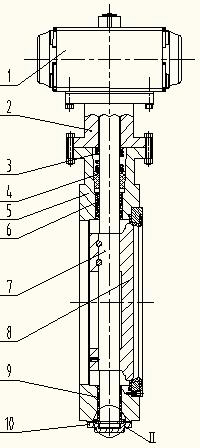
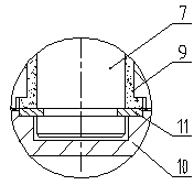
[0015] The high-temperature pulse reversing valve shown in the accompanying drawings includes drive cylinder 1, connecting body 2, valve stem 7, valve plate 8, valve body 5, valve stem upper bearing 6, valve stem lower bearing 9, lower end cover 10 and valve stem The shaft seal structure at the upper end; the drive cylinder 1 is fixedly connected to the upper end of the valve body 5 through the connecting body 2; the valve stem 7 is supported on the valve body 5 through the valve stem upper bearing 6 and the valve stem lower bearing 9; the shaft seal structure at the upper end of the valve stem is set Between the upper end of the valve body 5 and the valve stem 7, the upwardly opened conical cavity includes a seal 4 and a spring 3; the seal 4 is made of expanded graphite and is installed on the upper end of the valve body 5 and the v...


PUM


Abstract

The invention discloses a high-temperature pulse reversing valve which comprises a driving cylinder, a connector, a valve rod, a valve plate, a valve body, a valve-rod upper bearing, a valve-rod lower bearing, a lower end cover and a valve-rod upper shaft sealing structure, wherein the valve-rod upper shaft sealing structure is arranged in a conical cavity which is positioned between the upper end of the valve body and the valve rod and is expanded upward, and the valve-rod upper shaft sealing structure comprises a sealing element and a spring; the sealing element is a conical element which is made of expanded graphite and mounted in the conical cavity between the upper end of the valve body and the valve rod; the spring is arranged between the upper end face of the sealing element and the lower end face of the connector and compresses the sealing element to form an elastic self-sealing structure; the valve-rod upper bearing and the valve-rod lower bearing are graphite bearings and are made of high-strength leaching and roasting graphite. The high-temperature pulse reversing valve has further improvements as follows: a ring slot is formed in the lower end of the valve rod, and a split ring made of a wear-resistant material is arranged in the ring slot; the lower end face of the split ring is supported by the lower end cover. The high-temperature pulse reversing valve has the advantages of high temperature resistance, strong self lubrication, good sealing reliability, high reversing speed and long service life.

Description

technical field [0001] The invention relates to a butterfly valve, in particular to a reversing valve used on a regenerative burner. Background technique [0002] At present, the reversing valve used on the regenerative burner is a butterfly valve, and the valve stem is supported on the valve body by the upper bearing of the valve stem and the lower bearing of the valve stem; the upper bearing of the valve stem of the reversing valve of the existing regenerative burner, The bearing under the valve stem is made of metal material, which is not wear-resistant and has poor heat resistance. When the bearing is in a high temperature environment for a long time, the bearing made of metal material is prone to expansion and deformation, and the grease lubricant used in conjunction with it will inevitably be damaged. Cause pollution. Under the condition of high temperature and heavy load, the general calcium and sodium base grease loses its lubricating effect, and abnormal wear and te...

Claims


Application Information

Patent Timeline
Patent Type & Authority Applications(China)
IPC IPC(8): F16K1/32F16K1/226F16K41/02
CPCF16K1/2268F16K1/224
Inventor 周长荣张瑞之
Owner JIANGSU TENGTIAN IND FURNACE
Why Eureka
Try Eureka