Single-furnace multicolor float glass production line

A technology of float glass and production line, applied in the field of single-kiln multi-color float glass production line, which can solve the problems of difficult color change of melting furnace, lower production cost, and long color change cycle, so as to reduce energy consumption of single kiln and avoid pollution , The effect of reducing production costs

Inactive Publication Date: 2015-02-18
长兴旗滨玻璃有限公司
View PDF2 Cites 12 Cited by
  • Summary
  • Abstract
  • Description
  • Claims
  • Application Information

AI Technical Summary

Problems solved by technology

[0006] The invention solves the defects that the existing colored glass is colored at the position of the melting furnace, which causes difficulty in color changing in the melting furnace, long color changing period, waste of raw materials and scrapped glass, and provides a single kiln multi-color float method In the glass production line, the molten glass of the large-tonnage melting furnace is divided into multiple float glass production lines through the diverting device, and a coloring device is installed on each diverted production line, which does not affect the melting of the melting furnace, and at the same time reduces the influence of the coloring material on the glass liquid , or even if there is waste, it is only a waste of a production line, and will not cause waste of molten glass in the melting furnace, reducing production costs

Method used


Image

  • Single-furnace multicolor float glass production line
  • Single-furnace multicolor float glass production line
  • Single-furnace multicolor float glass production line

Examples


Embodiment 1

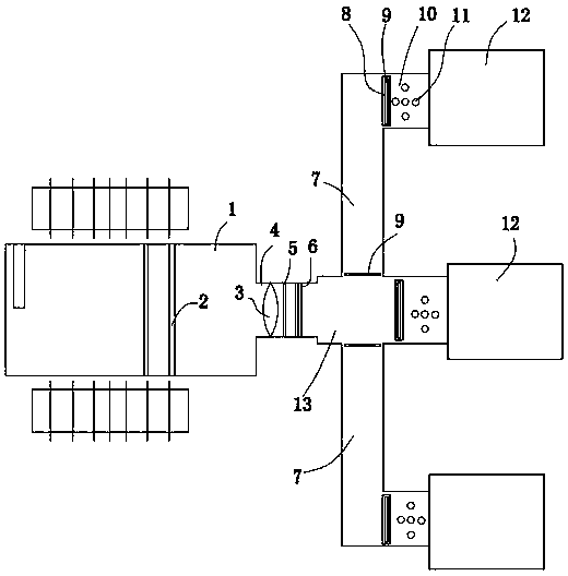
[0024] Embodiment 1: A kind of single kiln three-color float glass production line (see attached figure 1 ), including a large-tonnage melting furnace 1, connected to the primary neck 4 of the melting furnace. The melting furnace includes a feeding port, a melting zone, a small furnace, a regenerator, and a clarification chamber, and the clarification chamber is provided with a kiln rim bubbler 2 . A large water bag system 3, a horizontal mixing system 5 and a T-shaped hanging wall 6 are installed at the first-level neck. The first-stage neck is connected with a diversion device. The diversion device has three flow channels for diverting the glass liquid from the first-stage neck. Tin tank and subsequent devices, the sum of the pulling capacity of all runners corresponding to the production line matches the melting capacity of the glass melting furnace. The melting furnace built in this embodiment is 800t / d, and the pulling capacity of the production line corresponding to the...

Embodiment 2

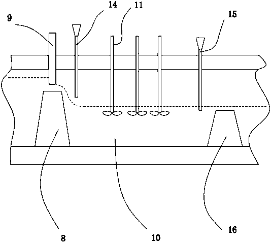
[0027] Example 2: A single-kiln three-color float glass production line, the difference from Example 1 is that a liquid flow kiln ridge 16 is arranged behind the coloring device in the secondary neck, and the height of the liquid flow kiln ridge is smaller than the return liquid The height of the kiln sill of the baffle, and the top surface of the liquid flow kiln sill is lower than the liquid level of the glass liquid at the secondary neck. A liquid pipe 15 is arranged on the front side of the liquid flow kiln sill in the secondary neck, the lower end of the liquid pipe is lower than the top of the liquid flow kiln sill, and the upper end of the liquid pipe is provided with a cover (see attached image 3 ). The number of liquid pipes is 4, arranged side by side in the secondary neck, and across the entire secondary neck. Refer to Example 1 for all the other structures.

Embodiment 3

[0028] Example 3: A single-kiln three-color float glass production line, the difference from Example 2 is that the liquid pipe overlaps with the stirring device of the coloring device, and the stirring device of the coloring device adopts a hollow shaft tube, which is The liquid pipe; the outer wall of the lower part of the shaft pipe is provided with a liquid hole; the stirring blade of the stirring device is fixed on the outer wall of the shaft pipe, and the liquid hole is arranged between the blade and the blade. The injection pipe is obliquely inserted into the secondary neck, the axis of the injection pipe intersects the inclined surface of the kiln sill, and the vertical projection of the outlet of the injection pipe falls on the inclined surface (see attached Figure 4 ). Refer to Example 1 for all the other structures.

[0029] According to the layout conditions of the production line, multiple outlets can be set on the horizontal flow channel, and each outlet is conn...


PUM


Abstract

The invention relates to a single-furnace multicolor float glass production line. The shortcomings of difficulty in color changing of a melting furnace, long coloring period and high raw material waste rate and glass scrap rate, which are caused by the coloring of conventional colored glass at the position of the melting furnace, are overcome. The production line comprises a large-tonnage melting furnace and a primary constricted neck, wherein a flow division device is connected behind the primary constricted neck, and is provided with a plurality of flow passages for dividing molten glass discharged from the primary constricted neck; a secondary constricted neck, a cooling part, a float glass production tin bath and a subsequent device are sequentially connected to each flow passage; a return liquid baffle plate is arranged at an inlet of the secondary constricted neck of each flow passage; a coloring device is arranged behind each return liquid baffle plate. According to the production line, the coloring devices are arranged at the inlets of the secondary constricted necks, and a formula for producing colored glass by virtue of a small-tonnage melting furnace can be utilized, so that the burden of a raw material processing procedure is reduced; coloring materials in each flow passage can be different, so that the aim of simultaneously producing different colored glass by one large-tonnage melting furnace is fulfilled.

Description

technical field [0001] The invention relates to a float glass production equipment, in particular to a single-kiln multi-color float glass production line capable of simultaneously producing glasses of different colors. Background technique [0002] At present, the production of colored glass in the float glass industry is mainly based on the practical body coloring technology. The advantage of this method is that the coloring is uniform, there is no color difference, and the appearance of the product is exactly the same color. With the maturity of the production technology, it is suitable for mass production. But in this method, a melting furnace can only produce glass of one color. To produce a variety of different colors of glass, it is necessary to replace the pigment for color transfer treatment. Changing the melting furnace from one color to another takes a long time for color change, during which scrapped glass is likely to be generated, resulting in waste of raw mat...

Claims


Application Information

Patent Timeline
Patent Type & Authority Applications(China)
IPC IPC(8): C03B18/12
CPCC03B18/12
Inventor 徐国平邵景楚官立民章凯雷明王炎春周红袁丽娜易节化郑志勇王巍
Owner 长兴旗滨玻璃有限公司
Why Eureka
Try Eureka