Automated Radiochemical Separation System for Burnup Measurement of Spent Fuel Elements

A radiochemical separation and spent fuel technology, applied in the field of automatic radiochemical separation system, can solve the problems of not being able to meet the needs of rapid measurement of component burnup, separation process yield, inconsistent decontamination factor, large dose of researchers, etc., to achieve The effect of shortening the time of dissolution and material liquid transfer, saving manpower consumption and shortening the seasoning time

Active Publication Date: 2017-01-25
CHINA INSTITUTE OF ATOMIC ENERGY
View PDF5 Cites 1 Cited by
  • Summary
  • Abstract
  • Description
  • Claims
  • Application Information

AI Technical Summary

Problems solved by technology

[0003] Currently, there are few published documents on radiochemical separation systems for fuel consumption measurement. Some documents disclose radiochemical separation methods, but they all have the following disadvantages: 1) There are many technical links and cumbersome separation processes, which cause a fuel consumption measurement to take 30 Many people participated; 2) The separation method was manually operated, which caused the researchers to receive a large dose (up to hundreds of Curies), and the yield and decontamination factor of the separation process were inconsistent.
3) Time-consuming
A fuel consumption measurement takes more than one year, which cannot meet the rapid development of nuclear power and the rapid measurement of component fuel consumption.
The automatic radiochemical separation system for fuel consumption measurement can solve the above problems, and there are no reports on this aspect at home and abroad.

Method used


Image

  • Automated Radiochemical Separation System for Burnup Measurement of Spent Fuel Elements
  • Automated Radiochemical Separation System for Burnup Measurement of Spent Fuel Elements

Examples


Embodiment 1

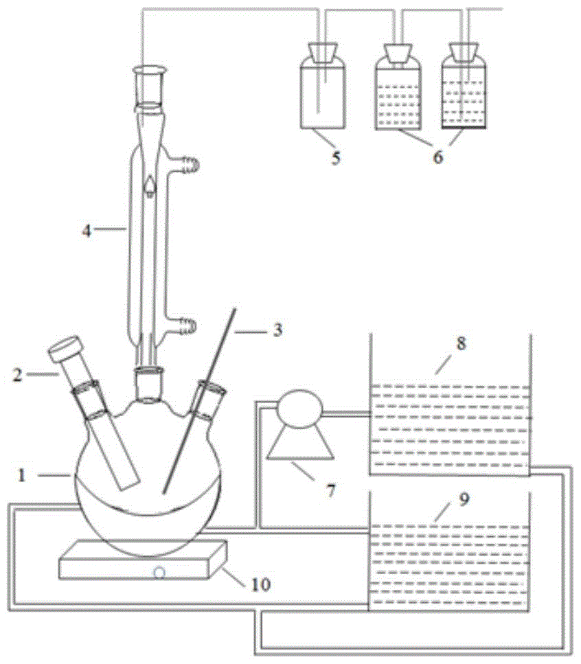
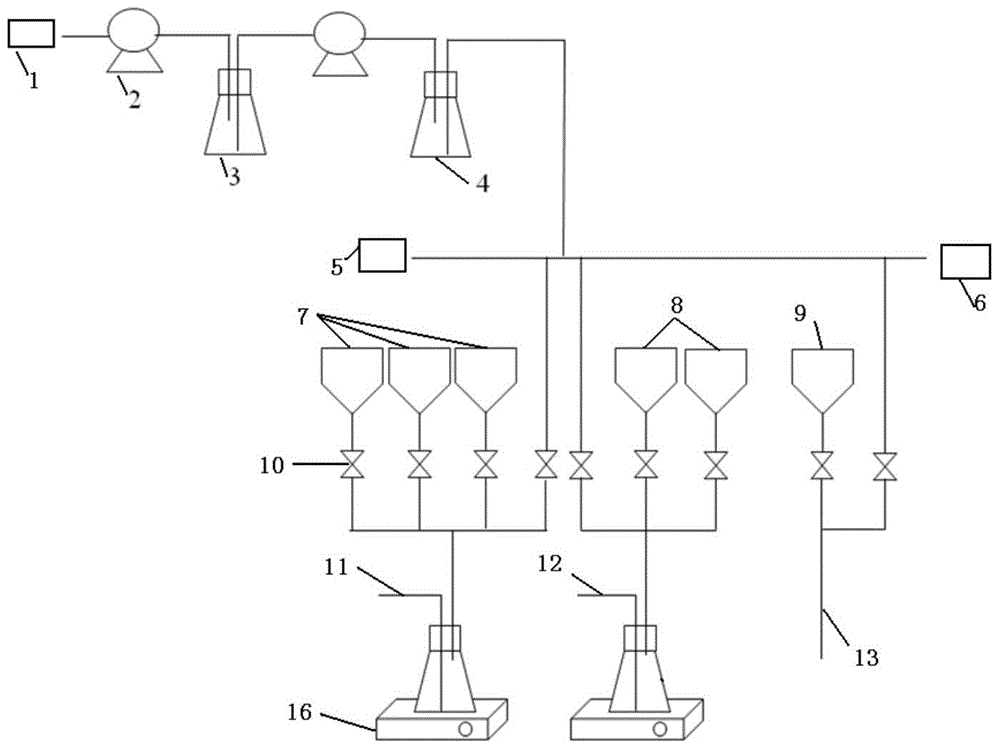
[0031] Automated radiochemical separation systems for burnup measurements of spent fuel elements, such as figure 1 and figure 2 shown. The system is composed of a dissolution unit, a seasoning unit, a separation unit and a control system. The dissolution unit, seasoning unit and separation unit are connected by a feed liquid delivery pipe; among them, the dissolution unit is as figure 1 As shown, the dissolver 1 is included, and the dissolver 1 is a double-layered round bottle-shaped structure with three necks, one of which is connected to the condenser tube 4, and the upper end of the condenser tube 4 is connected to the buffer bottle 5 and the liquid collection bottle 6 through a pipeline. Prevent the dissolving liquid from volatilizing into the environment during the dissolving process of the spent fuel element; one neck places the feeding pipe 2 with a honeycomb structure at the bottom, and the other neck inserts the feeding liquid delivery pipe 3 to realize the connecti...

Embodiment 2

[0061] The device and operation method are the same as in Example 1, except that the temperature of the high-temperature water bath is 75° C., and the temperature of the low-temperature water bath is 25° C.


PUM


Abstract

The invention belongs to the technical field of fuel consumption measurement of a spent fuel element in nuclear fuel circulation and discloses an automatic radiochemical separation system used for measuring fuel consumption of a spent fuel element. The system is composed of a dissolving unit, a material blending unit, a separation unit and a control system, wherein the dissolving unit, the material blending unit and the separation unit are connected with one another by a material liquid conveying pipe; the dissolving unit comprises a dissolving device; the dissolving device is of a double-layered three-neck round bottle structure; the separation unit mainly comprises a Mo separation column, a Nd separation column, a Pu separation column, a U separation column and Cs detection units; and the material blending unit comprises a concentration diluting device for diluting concentration, an isotope diluting device for diluting isotopes, a Pu material blending tank, a U material blending tank, a Nd material blending tank, a solenoid valve and a peristaltic pump for supplying power to material liquid. The system has the characteristics that monitoring body nuclides can be separated simultaneously, the separation time is short, the separation system is simple and the automatic separation can be realized.

Description

technical field [0001] The invention belongs to the technical field of burnup measurement of spent fuel elements in the nuclear fuel cycle, and in particular relates to an automatic radiochemical separation system for burnup measurement of spent fuel elements. Background technique [0002] The burnup value is an important parameter for evaluating reactor physical design, reactor power distribution, reactor safety operation, isotope production, and nuclear fuel element manufacturing, and is also an indispensable indicator for improving reactor fuel performance. There are non-destructive and destructive analysis methods for burnup analysis, and the most accurate burnup analysis method recognized internationally is destructive analysis. Because of different reactor types, different analysis purposes and requirements, component structures, cladding materials, uranium enrichment, and reactor operating conditions, etc., the burnup measurement methods are also different. But no ma...

Claims


Application Information

Patent Timeline
Patent Type & Authority Patents(China)
IPC IPC(8): G21C17/06
CPCG21C17/063Y02E30/30
Inventor 丁有钱宋志君杨素亮杨金玲
Owner CHINA INSTITUTE OF ATOMIC ENERGY
Why Eureka
Try Eureka