
Reactive phase modulation method for photovoltaic power station

A photovoltaic power station and phase modulation technology, which is applied in photovoltaic power generation, reactive power adjustment/elimination/compensation, flexible AC transmission system, etc. Power and other issues, to achieve the optimal adjustment and economic operation of the whole station, extensive engineering application value, and reduce the effect of flow

Inactive Publication Date: 2015-02-18
XJ ELECTRIC +1
View PDF5 Cites 29 Cited by
  • Summary
  • Abstract
  • Description
  • Claims
  • Application Information

AI Technical Summary

Problems solved by technology

Chinese patent application No. 201310368408.X discloses a reactive power voltage control method for photovoltaic power plants. Although the method takes into account the reactive capacity of the inverter and the rapidity of adjustment of multiple dynamic reactive power compensation devices, it is When distributing reactive power between devices, the proportional distribution of reactive power capacity is adopted, which does not consider the large area occupied by photovoltaic power plants and the scattered locations of photovoltaic arrays. The reactive power should be balanced locally to reduce the flow of reactive power; Factors such as geographical location, type of inverter, and optimal working range sacrifice the active power output capability of the inverter and do not consider the economic operation of the photovoltaic power station.

Method used


Image

  • Reactive phase modulation method for photovoltaic power station
  • Reactive phase modulation method for photovoltaic power station

Examples


Embodiment Construction

[0029] The present invention will be further introduced below in conjunction with the drawings and specific embodiments.

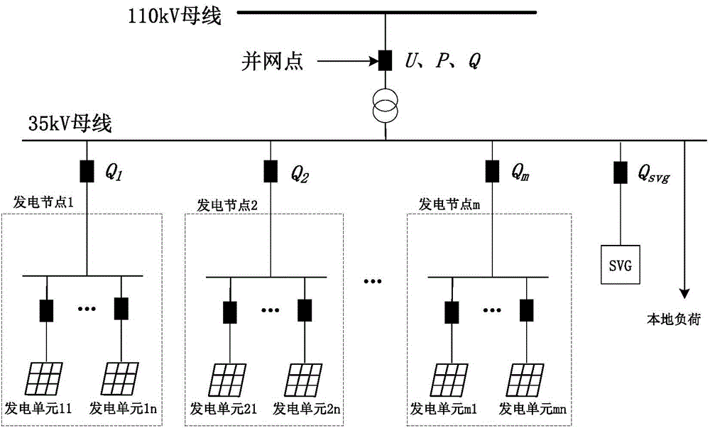
[0030] Such as figure 1 Shown is a schematic structural diagram of an embodiment of the grid-connected photovoltaic power generation system of the present invention. In the figure, the power generation nodes are obtained by grouping power generation units according to the geographic location of the photovoltaic array and the type of inverter. A power generation node contains n In a region of a MW-level power generation unit, n is usually 5-10. The power station of this embodiment has m power generation nodes in total.

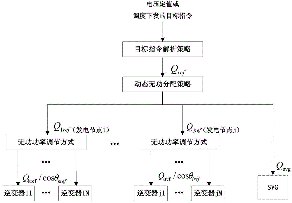
[0031] Such as figure 2 Shown is the principle diagram of the reactive power phase modulation method of the photovoltaic power station of the present invention. As can be seen from the diagram, the method includes the following steps:

[0032] (1) Convert the voltage setting value or the target command issued by the scheduling into the reactive...


PUM


Abstract

The invention discloses a reactive phase modulation method for a photovoltaic power station. Active power is emitted while own reaction output capacity of a grid-connected inverter is fully utilized as a supplement or a substitute of reaction compensation equipment, and configuration capacity of an SVG (static var generator) in an original photovoltaic power station is reduced to greatest extent or even without configuring the SVG, so that cost of the photovoltaic power station is greatly lowered; a reactive phase modulation subsystem uses a multi-target dynamic optimization algorithm to dynamically calculate a reactive target value of each power generating node, large occupied area of the photovoltaic power station and position dispersion of a photovoltaic array are taken into consideration, reactive in-place balance is realized, and flowing of reactive power is reduced; factors like geographical position of the photovoltaic array, type of the inverter and optimal working interval are taken into consideration, so that realization of reactive balance is guaranteed while maximization of active power output by the whole station is realized, whole-station optimal adjusting and economical running of the photovoltaic power station are realized, and the reactive phase modulation method has higher engineering application value.

Description

Technical field [0001] The invention belongs to the technical field of new energy control, and specifically relates to a grouping multicast and dynamic optimization control method for reactive power phase modulation of a photovoltaic power station by using the reactive power capacity of a grid-connected inverter. Background technique [0002] Large-scale photovoltaic grid-connected power generation is one of the important measures to solve the current energy shortage and environmental pollution. However, with the large-scale integration of photovoltaic power generation into the grid, the randomness, intermittentness and volatility of photovoltaic output have brought some negative effects on the safe and stable operation of the grid, among which the problem of reactive power and voltage is one of the significant problems. [0003] When the grid load is disturbed or the light intensity fluctuates, the grid-connected point voltage often fluctuates to a certain extent. The conventional...

Claims


Application Information

Patent Timeline
IPC IPC(8): H02J3/18
CPCH02J3/18Y02E10/56Y02E40/10
Inventor 崔丽艳孔波利吴双惠沈志广李现伟丁钊张鹏远王以笑卜银娜熊焰樊鹏李艳霞王兴安蒋怀贞
Owner XJ ELECTRIC
Learn More