Electric vehicle charger air-cooling system conducting precooling through chilled water and control method thereof
An air-cooling system, electric vehicle technology, applied in electric vehicles, battery circuit devices, cooling/ventilation/heating renovation, etc., can solve the problems of accelerated failure of devices, cracking of hard coatings, and reduced insulation performance of devices
- Summary
- Abstract
- Description
- Claims
- Application Information
AI Technical Summary
Problems solved by technology
Method used
Image

Examples
Embodiment 1
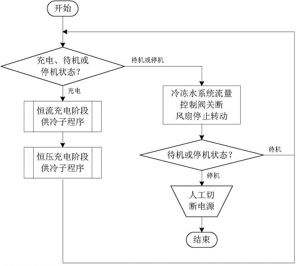
[0147] The program flow chart corresponding to the cooling subroutine in the constant current charging stage in Embodiment 1 is as follows Figure 4 Shown:
[0148] The cooling subroutine in the constant current charging stage is as follows: the chilled water in the cooling coil is at the lowest flow rate, and the air inlet fan and the air outlet fan are at the lowest speed; as the temperature of the power device gradually increases, gradually increase the chilled water flow rate; When the flow of chilled water reaches the maximum and the temperature of the power device is still at the temperature control upper limit, gradually increase the speed of the inlet fan and the fan of the outlet; when the flow of chilled water and the speed of the fan both reach the maximum, the temperature of the power device remains When it is at the upper limit of temperature control, maintain the maximum flow of chilled water and the maximum speed of the fan, the device will alarm and request man...
Embodiment 2
[0180] The cooling subroutine in the constant current charging stage in Embodiment 2 is the same as the cooling subroutine in the constant current charging stage in Embodiment 1.
[0181] The constant voltage charging stage dehumidification subroutine in embodiment 2 is as Figure 9 Shown:
[0182] The dehumidification subroutine in the constant voltage charging stage is: increase the flow rate of chilled water in the cooling coil to the maximum, maintain the original speed of the air inlet fan and the air outlet fan; gradually reduce the speed of the air inlet fan and the air outlet fan; when the temperature of the power device is higher than the air temperature outside the cabinet, the speed of the fan is reduced to the minimum, and when the temperature of the power device is at the lower limit of temperature control, keep the minimum speed of the fan and the maximum flow rate of chilled water; when the temperature of the power device is higher than the air temperature outs...
Embodiment 3
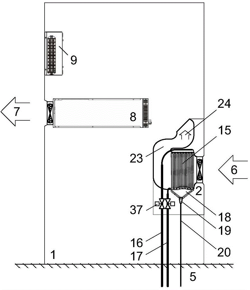
[0199] The structure and device layout of the dust removal and dehumidification device in embodiment 3 are as follows: Figure 12 Shown:
[0200] The dust removal and dehumidification device in the third embodiment makes the following changes on the basis of the air inlet precooling device in the second embodiment:
[0201] An electrostatic air filter 22 is installed in the air duct in the box body 2. Along the airflow direction in the air duct, the air inlet 6, protective shutters 21, electrostatic air filter 22, air intake fan, refrigeration coil 15, S-shaped Air duct 23 and the air outlet 24 of box body.
[0202] The electrostatic dust-proof filter has a capture efficiency of more than 99% for small-sized dust with a particle size greater than 0.5 μm, and its filtering effect on PM10 and PM2.5 suspended particulate matter is significantly better than traditional dust-proof filters; The wind resistance is only one-third of that of the traditional dust-proof filter. When th...
PUM
 Abstract
Description
Claims
Application Information
 - R&D
- Intellectual Property
- Life Sciences
- Materials
- Tech Scout
- Unparalleled Data Quality
- Higher Quality Content
- 60% Fewer Hallucinations
Browse by: Latest US Patents, China's latest patents, Technical Efficacy Thesaurus, Application Domain, Technology Topic, Popular Technical Reports.
© 2025 PatSnap. All rights reserved.Legal|Privacy policy|Modern Slavery Act Transparency Statement|Sitemap|About US| Contact US: help@patsnap.com