Upper cone body of cerement bin and manufacturing process of upper cone body

A manufacturing process and cement silo technology, applied in the field of machinery, can solve the problems of long production cycle, waste of solder resources, and high cost of the silo, improve processing accuracy, product quality and aesthetics, shorten production cycle, and environmentally friendly processing methods. Effect

Inactive Publication Date: 2015-02-25
潍坊金河机械有限公司
View PDF5 Cites 0 Cited by
  • Summary
  • Abstract
  • Description
  • Claims
  • Application Information

AI Technical Summary

Problems solved by technology

[0002] At present, the cement silos commonly used in the market generally have a capacity of several hundred tons, are relatively large, and need to be welded in sections. They are roughly divided into an upper cone, a middle cylinder, and a lower cone, all of which are assembled by pieces. In the prior art, the flanges are generally welded directly around the silo pieces. This connection method requires a large number of welding workers and solder. Pollution and waste of solder resources. In addition, due to manual welding, there will inevitably be deviations between the silo pieces. After the overall assembly, the gaps are too large and water seepage is easy, there are many welds, and the entire silo is skewed. The silo production cycle of the method is long and the cost is high
If the silo pieces of the upper cone, the middle cylinder and the lower cone are directly welded, the above-mentioned shortcomings will be more prominent

Method used


Image

  • Upper cone body of cerement bin and manufacturing process of upper cone body
  • Upper cone body of cerement bin and manufacturing process of upper cone body

Examples


Embodiment 1

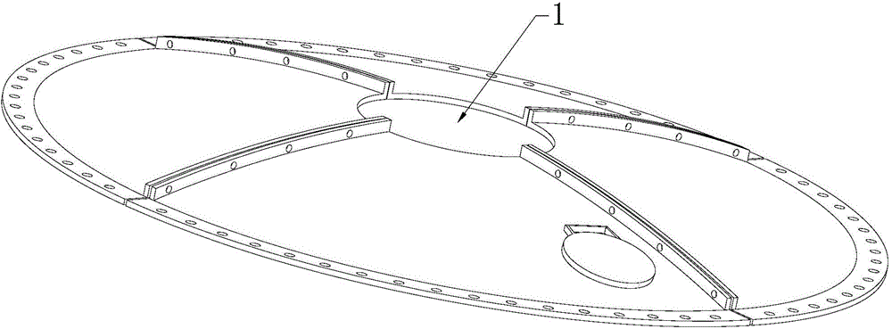
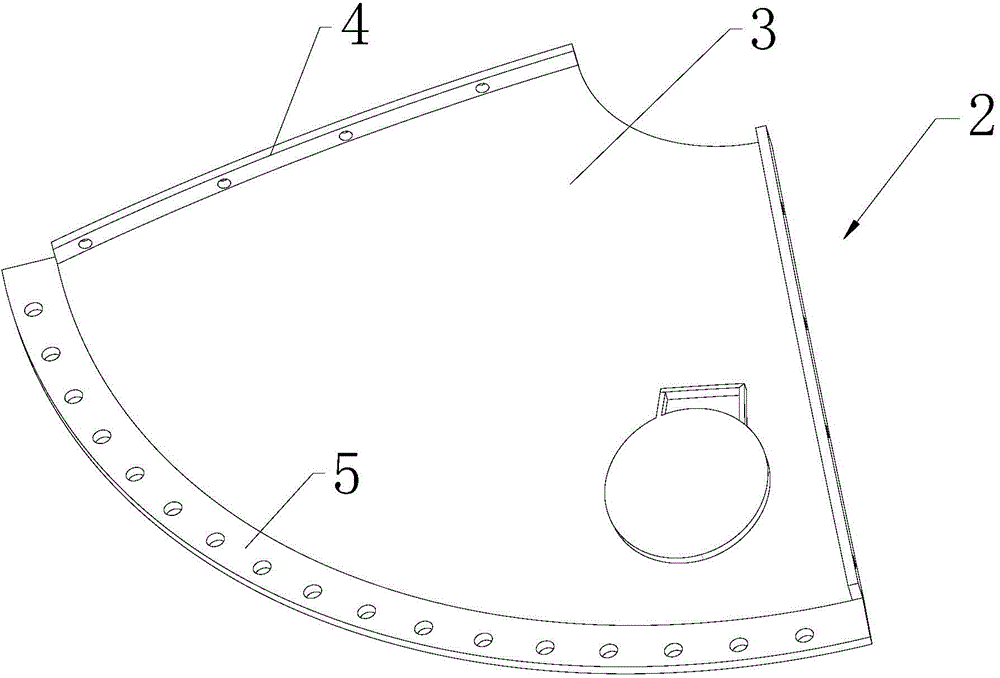
[0016] Such as figure 1 and figure 2 Commonly shown, the upper cone of the cement silo, the upper cone 1 includes several upper cone splicing modules 2 of the same size, and several upper cone splicing modules 2 are assembled to form the upper cone 1, and each upper cone splicing module 2 Both include an upper cone splicing module body 3, the left and right sides of the upper cone splicing module body 3 are respectively provided with an upper cone strip flange 4 made by integral molding of a hydraulic press, and two adjacent upper cone splicing modules 2 The upper cone bar flanges 4 are installed together by fasteners, and the lower end of each upper cone splicing module body 3 is welded with an upper end fixedly connected to the upper end of the middle cylinder (not marked in the figure). Conical arc flange 5.

[0017] In order to strengthen the structural strength, several welded reinforcement plates (not shown) are arranged between the two arc-shaped flanges of the upper...

Embodiment 2

[0022] The manufacturing process of the upper cone of the cement silo includes the following steps: using a numerical control machine tool to cut out a number of trapezoidal metal plates required for making the upper cone splicing module 2, and making the trapezoidal metal plates required for the upper cone splicing module 2 on the left and right sides Use the drilling die to drill holes, then use the upper cone splicing module stamping die to bend the trapezoidal metal sheet into an arc shape through a hydraulic press, and punch out strip flanges on both sides of the metal sheet, and then the strip flanges on both sides The flange is fixed, and the lower end of the metal plate is welded to the arc-shaped flange, and finally the two shaped flanges are loosened, and the manufacture of an upper cone splicing module 2 is completed.

[0023] Further, several reinforcing plates are welded between the two arc-shaped flanges of the upper cone splicing module 2 and the wall of the uppe...


PUM


Abstract

The invention provides an upper cone body of a cerement bin and a manufacturing process of the upper cone body. The upper cone body comprises a plurality of upper cone body splicing modules which are the same in size. The upper cone body splicing modules are assembled into the upper cone body. Each upper cone body splicing module comprises an upper cone body splicing module body, wherein upper cone body strip-shaped flanges are arranged on the left side and the right side of the upper cone body splicing module body respectively, and the upper cone body strip-shaped flanges are integrally formed through a hydraulic machine. The upper cone body strip-shaped flanges of every two adjacent upper cone body splicing modules are installed together through fastening pieces. An upper cone body arc-shaped flange is welded to the lower end of each upper cone body splicing module body. Each upper cone body arc-shaped flange is fixedly connected with the upper end of a middle cylinder. By means of the upper cone body and the manufacturing process, the production cycle is greatly shortened, cost is greatly reduced, all bin bodies are the same in size, the upper cone bodies can be produced in batches, standardization is achieved, transportation is convenient, and the upper cone body can be rapidly assembled on site.

Description

technical field [0001] The invention relates to the field of machinery, in particular to an upper cone of a cement silo and a manufacturing process thereof. Background technique [0002] At present, the cement silos commonly used in the market generally have a capacity of several hundred tons, are relatively large, and need to be welded in sections. They are roughly divided into an upper cone, a middle cylinder, and a lower cone, all of which are assembled by pieces. In the prior art, the flanges are generally welded directly around the silo pieces. This connection method requires a large number of welding workers and solder. Pollution and waste of solder resources. In addition, due to manual welding, there will inevitably be deviations between the silo pieces. After the overall assembly, the gaps are too large and water seepage is easy, there are many welds, and the entire silo is skewed. The production cycle of the silo in this way is long and the cost is high. If direct...

Claims


Application Information

Patent Timeline
IPC IPC(8): B65D90/02
CPCB65D90/025B65D90/08
Inventor 王玺铜王永祥
Owner 潍坊金河机械有限公司
Why Eureka
Try Eureka