Multi-return-stroke heat-exchanging type biomass boiler

A biomass boiler and multi-return technology, which is applied in steam boilers, water tube steam boilers, steam generation, etc., can solve the problems of large equipment area, easy to block boilers, and high thermal efficiency, so as to improve recovery efficiency and protect against being Dissipation, the effect of improving thermal efficiency

Active Publication Date: 2015-02-25
HUAIHUA QIXIAO ENERGY SAVING TECH +1
View PDF6 Cites 8 Cited by
  • Summary
  • Abstract
  • Description
  • Claims
  • Application Information

AI Technical Summary

Problems solved by technology

[0002] The use of existing biomass boilers can generally be divided into: feeding system, blast and induced air system, boiler combustion system and dust removal system due to the characteristics of uniform thickness of biomass fuel, easy to catch fire, fast combustion time, and light dust after combustion. Due to the clear division of labor of various systems and the relative independence of each system equipment, the existing biomass boilers inevitably have a large area of ​​equipment, troublesome installation, long paths for heat energy circulation, and waste of heat energy utilization.
[0003] Moreover, most of the existing boiler flues are vertically arranged. The small boilers that people use now are generally vertical water tube or fire tube boilers. Factors such as furnace space and flue resistance restrict the arrangement of the tubes, so the thermal efficiency of small boilers has always been Much lower than large boilers and horizontal boilers
The catering industry and small family workshops need small boilers, but they require small size, fast SAIC, and high thermal efficiency. The current small biomass boilers are difficult to meet their requirements
The low density of the water pipes installed in the existing boiler furnace is because if it is dense, the smoke and dust fall on the top of the water pipes and it is easy to block the boiler. In practical applications, the thermal efficiency of low-density water pipes is low.

Method used


Image

  • Multi-return-stroke heat-exchanging type biomass boiler
  • Multi-return-stroke heat-exchanging type biomass boiler
  • Multi-return-stroke heat-exchanging type biomass boiler

Examples


Embodiment Construction

[0035] In order to enable those skilled in the art to better understand the technical solution of the present invention, the present invention will be described in detail below in conjunction with the accompanying drawings. The description in this part is only exemplary and explanatory, and should not have any limiting effect on the protection scope of the present invention. .

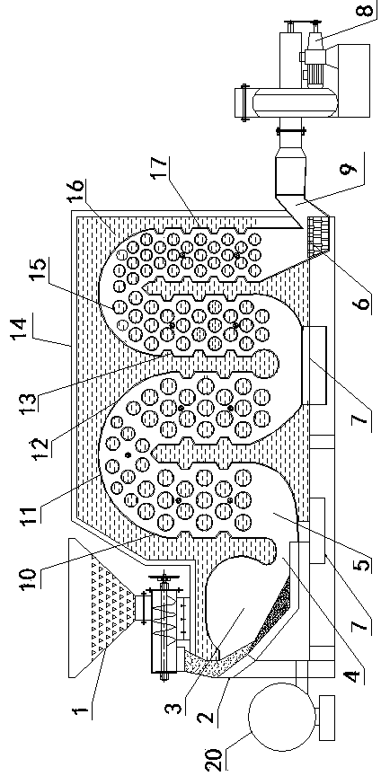
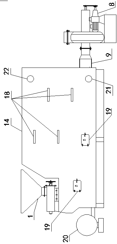
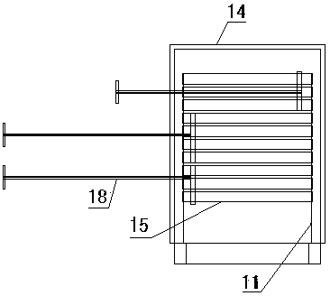
[0036] see figure 1 , figure 2 , image 3 , Figure 4, a multi-return heat-exchanging biomass boiler, this device includes a boiler body and a blast and air induction system, the boiler body includes a feeder 1, a double furnace mechanism, a multi-return densely distributed water tube furnace 11, and a smoke exhaust Pipe 9, the water tank 16 arranged on the outside of the double furnace mechanism and the furnace, and the insulation layer 14 arranged on the outside of the water tank. The inlet of the double furnace mechanism is connected with the feeder 1 and the blower 20, the outlet of the double...


PUM


Abstract

The invention discloses a multi-return-stroke heat-exchanging type biomass boiler. The biomass boiler comprises a boiler body and an air blowing and inducing system, and is characterized in that the boiler body comprises a feeder, a double-combustion-chamber mechanism, a multi-return-stroke densely distributed water pipe boiler furnace, a smoke exhausting pipe, a water tank arranged outside the double-combustion-chamber mechanism and the boiler furnace, and a thermal insulation layer arranged on the exterior of the water tank. The inlet of the double-combustion-chamber mechanism is connected with the feeder and an air blower, and the outlet of the double-combustion-chamber mechanism is connected with the inlet of the boiler furnace. The outlet of the boiler furnace is connected with the smoke exhausting pipe and an induced draft fan. The multi-return-stoke heat-exchanging type biomass boiler is high in heat efficiency, safe, reliable, convenient to install and small in occupied area.

Description

technical field [0001] The invention belongs to the field of boilers, in particular to a multi-pass heat exchange biomass boiler. Background technique [0002] The use of existing biomass boilers can generally be divided into: feeding system, blast and induced air system, boiler combustion system and dust removal system due to the characteristics of uniform thickness of biomass fuel, easy to catch fire, fast combustion time, and light dust after combustion. Due to the clear division of labor of various systems and the relative independence of each system equipment, the existing biomass boilers inevitably have the disadvantages of large equipment footprint, troublesome installation, long paths for heat energy circulation, and waste of heat energy utilization. [0003] Moreover, most of the existing boiler flues are vertically arranged. The small boilers that people use now are generally vertical water tube or fire tube boilers. Factors such as furnace space and flue resistanc...

Claims


Application Information

Patent Timeline
Patent Type & Authority Applications(China)
IPC IPC(8): F22B15/00F23B40/00F23K3/00
Inventor 梁书元谢璇秋子
Owner HUAIHUA QIXIAO ENERGY SAVING TECH
Why Eureka
Try Eureka