500kv transformer shock insulation structure and installation method

An installation method and transformer technology, which is applied in transformer/reactor installation/support/suspension, inductance/transformer/magnet manufacturing, shock absorber, etc., can solve high earthquake vulnerability, oil leakage, and inaccurate loss calculation, etc. problem, to achieve the effect of improving the earthquake resistance

Inactive Publication Date: 2015-02-25
SOUTHWEST ELECTRIC POWER DESIGN INST OF CHINA POWER ENG CONSULTING GROUP CORP
View PDF7 Cites 9 Cited by
  • Summary
  • Abstract
  • Description
  • Claims
  • Application Information

AI Technical Summary

Problems solved by technology

[0005] Therefore, when the existing 500kY transformer and its installation method deal with severe vibrations such as high earthquake intensity of 8 to 9 degrees, it will undoubtedly cause a relatively severe safety test for the high-voltage and low-voltage bushings and oil conservator installed on the top of the transformer oil tank. For example, during the Wenchuan Earthquake and the Ya’an Earthquake in China, the sudden violent vibrations caused problems such as rupture, damage, and oil leakage of high-voltage and low-voltage bushings and oil conservators on many transformers, resulting in long-term power outages for transformers. The various losses caused by this cannot be accurately calculated.
After investigation, in view of the current problem of high earthquake vulnerability of transformers, major transformer manufacturing companies at home and abroad have been unable to continue to improve the overall seismic level of transformers by changing the structure of high-voltage and low-voltage bushings and oil conservators.

Method used


Image

  • 500kv transformer shock insulation structure and installation method
  • 500kv transformer shock insulation structure and installation method
  • 500kv transformer shock insulation structure and installation method

Examples


Embodiment Construction

[0030] In order to make the objectives, technical solutions, and advantages of the present invention clearer, the following describes the present invention in detail with reference to the accompanying drawings and specific embodiments. It should be understood that the specific embodiments described herein are only used to explain the present invention, but not to limit the present invention.

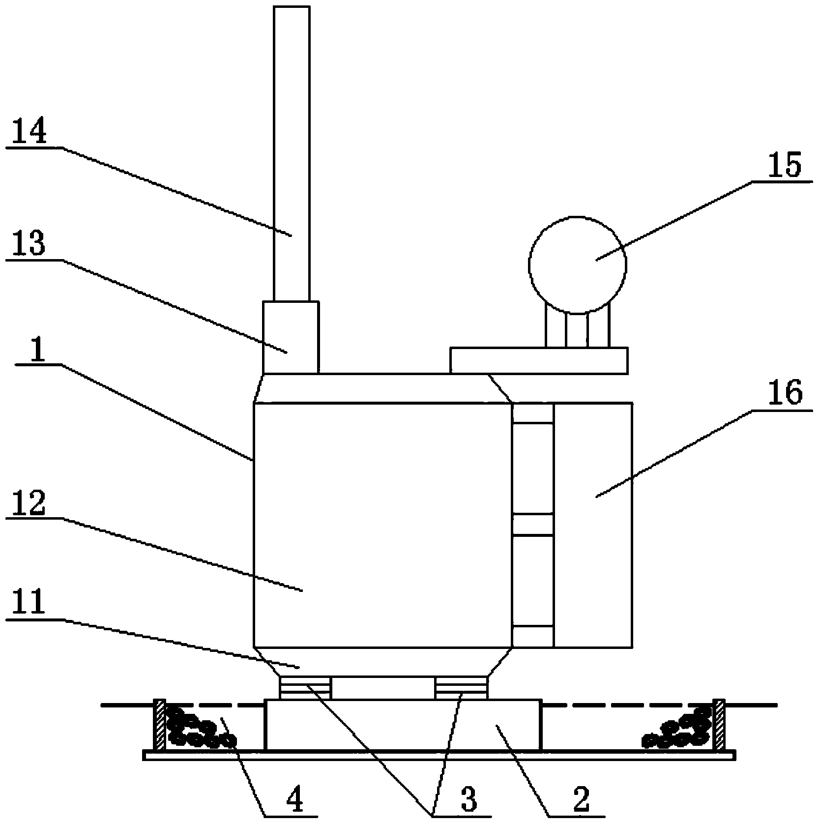
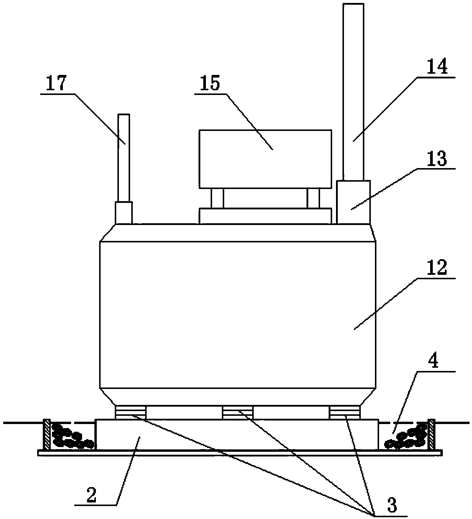
[0031] Such as figure 1 , figure 2 The 500kY transformer isolation structure shown includes transformer 1, base 2, and isolator 3. The transformer 1 is mainly composed of a base 11, an oil tank 12, an iron core, a winding coil, a riser 13, a high voltage bushing 14, and The oil pillow 15, the radiator 16 and the low-voltage bushing 17 are composed of the raised seat 13, the high-voltage bushing 14, the oil pillow 15 and the low-pressure bushing 17 are all located on the top of the oil tank 12. The iron core and the winding coil are installed in the oil tank 12. Inside, the radiator 16 is i...


PUM


Abstract

The invention provides a 500kV transformer shock insulation structure and an installation method. The shock insulation structure comprises a transformer, a foundation and a plurality of shock insulators, wherein the upper end and the lower end of each shock insulator are fixedly connected with a transformer base and the foundation respectively. The installation method of the shock insulation structure mainly includes the steps that firstly, a connecting component is installed on the foundation; secondly, the bottom of each shock insulator is fixedly connected with the connecting component; thirdly, the transformer is placed at the tops of the shock insulators, and the transformer base is fixedly connected with the shock insulators. By adoption of the 500kV transformer shock insulation structure and the installation method, a transformer body can be insulated from the foundation, the transformer can be separated from the earthquake ground movement possibly causing destruction, the earthquake energy spreading path is cut off, earthquake energy transmitted to damageable parts, such as high-tension bushings, oil conservators and low-tension bushings, at the top of the transformer is reduced as much as possible, the amplifying effect of an oil tank is offset, shock resistance of the transformer is greatly improved, and it is ensured that the transformer can still operate safely even in areas of eight to nine degrees of seismic intensity.

Description

Technical field [0001] The invention relates to the technical field of 500kY transformer seismic isolation in the power industry, and in particular to a 500kY transformer seismic isolation structure and an installation method suitable for areas with high seismic intensity of 8 to 9 degrees. Background technique [0002] For transformers installed in areas with high seismic intensity such as 8 to 9 degrees, the damage caused by sudden earthquakes to transformers and other power facilities is catastrophic, except for the high cost of post-disaster recovery, reconstruction and huge losses caused by power outages. In addition, as an important part of the lifeline project, once the power system fails or is destroyed, the resulting power interruption will not only seriously affect the normal earthquake relief work, but also may cause secondary disasters such as fires. [0003] The current common 500kY transformer is mainly composed of oil tank, iron core, winding coil, radiator, oil pill...

Claims


Application Information

Patent Timeline
Patent Type & Authority Applications(China)
IPC IPC(8): H01F27/06F16F15/02F16F7/00H01F41/00
Inventor 李龙才吴怡敏余波冯小明张映桢曹尹樊艳蔡德江钟山周德才隋权邹家勇朱大鹏尹大千邢毅冯千秀骆玲冯川龚琳珺余露月李珊珊刘焘王振华包维瀚
Owner SOUTHWEST ELECTRIC POWER DESIGN INST OF CHINA POWER ENG CONSULTING GROUP CORP
Why Eureka
Try Eureka