Fine particle classification measurement device, sample creation device with uniform particle concentration, and nanoparticle film forming device

A technology for measuring devices and particles, which is applied in the direction of measuring devices, particle size analysis, sampling devices, etc., can solve the problems of unavoidable membrane damage and inability to eliminate uneven distribution of particles, and achieves small damage, clear particle size range, and The effect of low kinetic energy

Inactive Publication Date: 2015-02-25
SHIMADZU SEISAKUSHO CO LTD
View PDF20 Cites 10 Cited by
  • Summary
  • Abstract
  • Description
  • Claims
  • Application Information

AI Technical Summary

Problems solved by technology

Conventional wet methods such as spin coating cannot eliminate the uneven distribution o...

Method used


Image

  • Fine particle classification measurement device, sample creation device with uniform particle concentration, and nanoparticle film forming device
  • Fine particle classification measurement device, sample creation device with uniform particle concentration, and nanoparticle film forming device
  • Fine particle classification measurement device, sample creation device with uniform particle concentration, and nanoparticle film forming device

Examples


Embodiment Construction

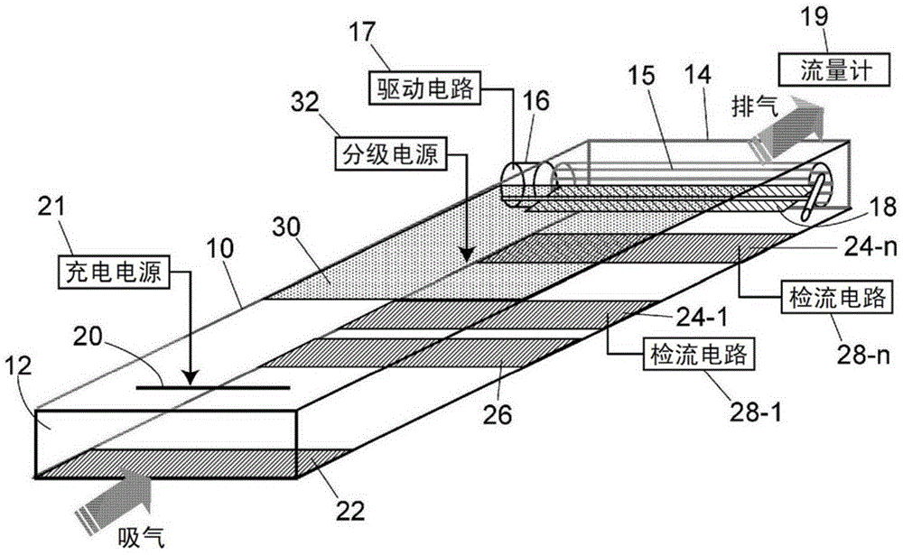
[0077] figure 1 It roughly shows an example of the particle classification measurement device of the present invention. The flow path 10 has openings at the inlet 12 and the outlet 14, and has a flat shape with a rectangular cross section in both the flow direction and the width direction of the flow path. The size and shape of the flow path are not particularly limited, for example, it is a flat rectangular parallelepiped with a length (height) of 4 mm, a width (width of flow path) of 250 mm, and a depth (length of flow path) of 450 mm.

[0078] On the outlet 14 side of the flow path 10, a fan 15 is arranged as an air blowing mechanism for sucking the sample. A motor 16 that rotates the fan 15 is driven by a drive circuit 17 . On the sample gas suction side of the fan 15, a manual butterfly valve is provided as a flow rate adjustment valve 18, and the flow rate of the sample gas can be changed by adjusting the flow rate control valve 18. The fan 15 sucks air evenly across ...


PUM


Abstract

A charging apparatus is positioned at an intake side of a parallel flow path through which it is possible for a sample gas which flows therein to become a laminar flow. The charging apparatus comprises a discharge electrode and charges fine particles within the sample gas. On one face of a pair of opposing faces of the flow path, either one or a plurality of suction-side electrodes are positioned downstream of the charging apparatus in locations of mutually different lengths from the intake of the flow path along the flow path direction. A classification electrode is positioned upon the other face of the pair of opposing faces of the flow path. The classification electrode is positioned opposite the suction-side electrodes, and an electric field is emitted which attracts charged fine particles in the sample gas which flows between the classification electrode and the suction side electrodes toward the suction-side electrodes.

Description

technical field [0001] The present invention relates to a particle measurement device suitable for monitoring the concentration of nanoparticles in automobile exhaust gas, building sanitation management, labor safety and sanitation, etc., and particularly relates to a particle classification measurement device for measuring particles according to particle size classification, and a tester for uniform particle concentration distribution. Sample production device, and nanoparticle film film forming device. Background technique [0002] As a counting device for the number of microparticles with a small particle size of several nanometers to tens of nanometers or more, it is known to use the microparticles as the nucleus to condense working fluid vapors such as water and butanol around them to increase the diameter of the microparticles. Light is irradiated, and the number of scattered light pulses at a specific scattering angle is detected to measure the CPC (condensing particl...

Claims


Application Information

Patent Timeline
IPC IPC(8): G01N15/02G01N1/02G01N27/60
CPCG01N15/0656G01N15/0266B03C3/017B03C3/08B03C3/12B03C3/38B03C3/41B03C3/47G01N1/2202G01N15/0606G01N2001/2223G01N2015/0038G01N2015/0046
Inventor 奥田浩史
Owner SHIMADZU SEISAKUSHO CO LTD
Why Eureka
Try Eureka