Automatic welding method based on 3D model and machine vision

A three-dimensional model and automatic welding technology, which is applied to welding equipment, welding equipment, auxiliary welding equipment, etc., can solve the problems of not having a wide range of automatic welding seam positions, not having real-time adjustment control, and being unable to adapt to thermal deformation, etc., to achieve Realize the effects of welding operation, fast positioning speed, and overcoming errors in processing and assembly

Active Publication Date: 2016-04-27
南京曼新智能科技有限公司
View PDF12 Cites 2 Cited by
  • Summary
  • Abstract
  • Description
  • Claims
  • Application Information

AI Technical Summary

Problems solved by technology

These two types of welding robots do not have the function of real-time adjustment and control, and cannot adapt to workpiece processing and assembly errors and thermal deformation caused by welding (see "Xu Yanling, Robot GTAW based on vision and arc sensing technology for three-dimensional welding seam real-time tracking Control Technology Research, Shanghai, Shanghai Jiaotong University Doctoral Dissertation, published in 2013")
At present, intelligent welding systems with real-time tracking function have been researched, but these systems need to move the welding torch to the starting point of the welding seam for initialization, and do not have the function of automatically finding the welding seam position in a wide range (see "Wu Lin, Chen et al. Rare Book, Intelligent Welding Technology, National Defense Industry Press, published in 2000")
[0003] A major defect of the current welding seam visual tracking technology is that it is necessary to manually initialize the position of the welding torch so that it is near the starting point of welding.

Method used


Image

  • Automatic welding method based on 3D model and machine vision
  • Automatic welding method based on 3D model and machine vision

Examples


Embodiment Construction

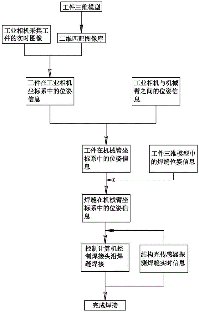
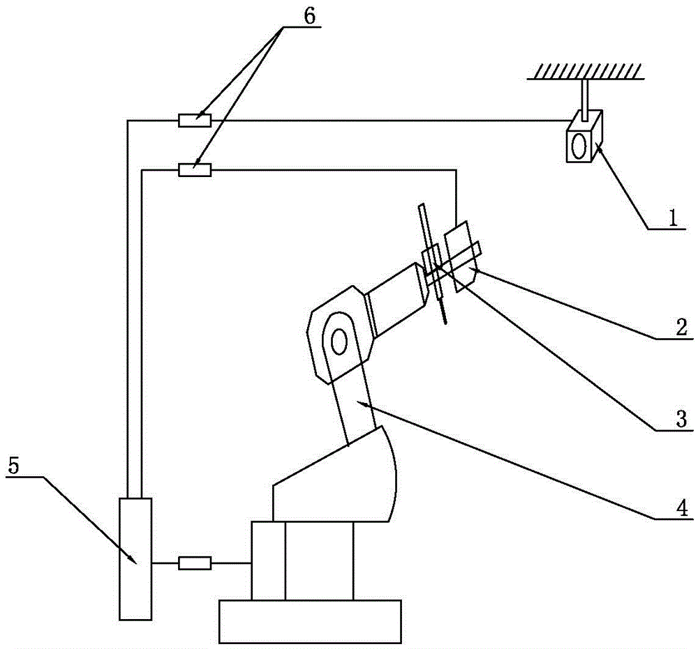
[0022] Such as figure 2 As shown, it is an automatic welding device based on a three-dimensional model and machine vision. Its structure mainly includes a mechanical arm 4 with six degrees of freedom. The six degrees of freedom are linear motions in the directions of X, Y and Z axes. , and rotation around the X, Y, and Z axes; the mechanical arm 4 holds the welding torch 3, and the end of the mechanical arm 4 is provided with a structured light sensor 2. The device also includes an industrial camera 1, and the workpiece collected by the industrial camera 1 The image signal is transmitted to the control computer 5, and the control computer 5 compares the plane figure converted from the three-dimensional model of the workpiece with the image signal collected by the industrial camera to obtain the pose information of the workpiece in the coordinate system of the industrial camera, and then according to the pose information Determine the position and orientation information of th...


PUM


Abstract

The invention relates to an automatic welding method based on a three-dimensional model and machine vision and a welding device based on the three-dimensional model and the machine vision, relating to the technical field of welding. An industrial camera is used for acquiring an image of a workpiece to be welded; three-dimensional match is carried out and the workpiece to be welded is positioned according to the three-dimensional model of the workpiece; a welding line is positioned according to welding line information in the three-dimensional model; the welding line is accurately positioned by using a structure optical sensor; a movement track of a welding gun is adjusted according to the accurate position of the welding line so as to accurately track and weld the welding line. According to the automatic welding method, an automatic positioning and tracking function of the welding line can be realized, and the reliability of tracking the welding line and the tracking precision are improved. The problems that the welding precision is influenced, caused by the fact that the workpiece is warped by thermal deformation in a welding process and the like are solved; the adjustment and the adaptation can be carried out very well and the welding quality is improved.

Description

technical field [0001] The invention relates to a welding device and a welding method, belonging to the technical field of welding. Background technique [0002] In the prior art, most of the welding robots used at home and abroad belong to teaching reproduction with low intelligence level and a small amount of off-line programming robots. These two types of welding robots do not have the function of real-time adjustment and control, and cannot adapt to workpiece processing and assembly errors and thermal deformation caused by welding (see "Xu Yanling, Robot GTAW based on vision and arc sensing technology for three-dimensional welding seam real-time tracking Control Technology Research, Shanghai, Doctoral Dissertation of Shanghai Jiao Tong University, published in 2013"). At present, intelligent welding systems with real-time tracking function have been researched, but these systems need to move the welding torch to the starting point of the welding seam for initialization,...

Claims


Application Information

Patent Timeline
Patent Type & Authority Patents(China)
IPC IPC(8): B23K37/00B23K37/02G06F17/50
CPCB23K9/1274
Inventor 朱文俊董远强王鹏李福东李林刘志强
Owner 南京曼新智能科技有限公司
Why Eureka
Try Eureka