Multi-rotor-wing patrolling aircraft and power transmission line patrolling system

A multi-rotor and aircraft technology, applied in aircraft, rotorcraft, overhead line/cable equipment, etc., can solve the problem that multi-rotor aircraft cannot accurately mount the ground wire, etc., to avoid difficulty in obstacle crossing, improve efficiency and accuracy The effect of the ground wire mount function

Active Publication Date: 2015-03-04
HENAN POWER TRANSMISSION & TRANSFORMATION CONSTR CO LTD +1
View PDF7 Cites 25 Cited by
  • Summary
  • Abstract
  • Description
  • Claims
  • Application Information

AI Technical Summary

Problems solved by technology

[0009] The main purpose of the embodiments of the present invention is to provide a multi-rotor inspection aircraft and transmission line inspection system, which integrates unmanned aerial vehicle technology and online robot technology and applies them to the field of transmission line inspection, and also has the ability to fly outside the ground wire. , walking on the ground wire, inspecting the ground wire, pole tower, fittings, channels, etc. for defects, etc., and solved the problem that the multi-rotor aircraft used for the inspection of the existing transmission line cannot accurately mount the ground wire

Method used


Image

  • Multi-rotor-wing patrolling aircraft and power transmission line patrolling system
  • Multi-rotor-wing patrolling aircraft and power transmission line patrolling system
  • Multi-rotor-wing patrolling aircraft and power transmission line patrolling system

Examples


Embodiment 1

[0076] This embodiment is designed for the disassembly and assembly of the multi-rotor flying device.

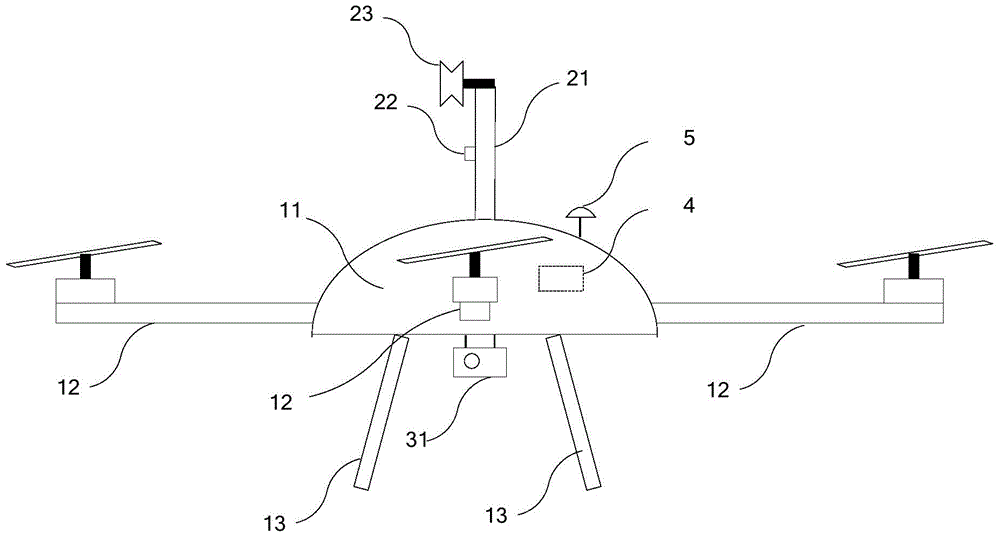
[0077]In this embodiment, the nacelle is an oblate cabin structure, and a plurality of openings are evenly arranged along its circumference, and the plurality of openings correspond to the plurality of rotors one by one; the landing gear can be, but not limited to, fixed on the The bottom of the cabin.

[0078] The rotor in this embodiment specifically includes: a rotor bracket, a brushless motor, a propeller and an anti-collision cover. Wherein, one end of the rotor bracket is plugged and fixed in the corresponding opening; the brushless motor, the propeller and the anti-collision cover are installed on the rotor bracket; Driven by the brush motor to rotate and generate lift; the anti-collision cover is arranged on the outside of the propeller.

[0079] In this embodiment, each rotor and the nacelle are assembled and disassembled through the plug connection between the ro...

Embodiment 2

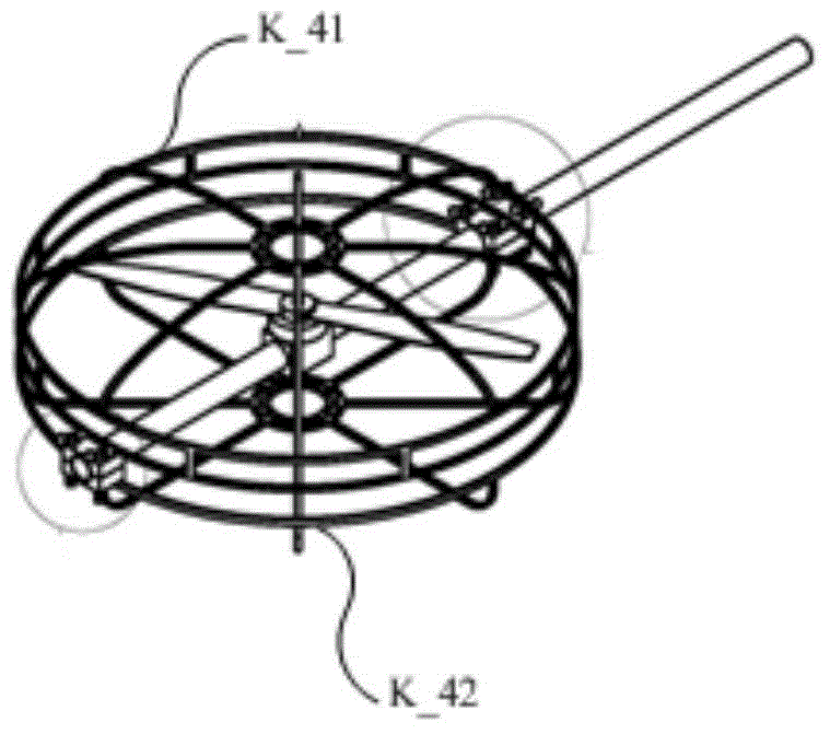
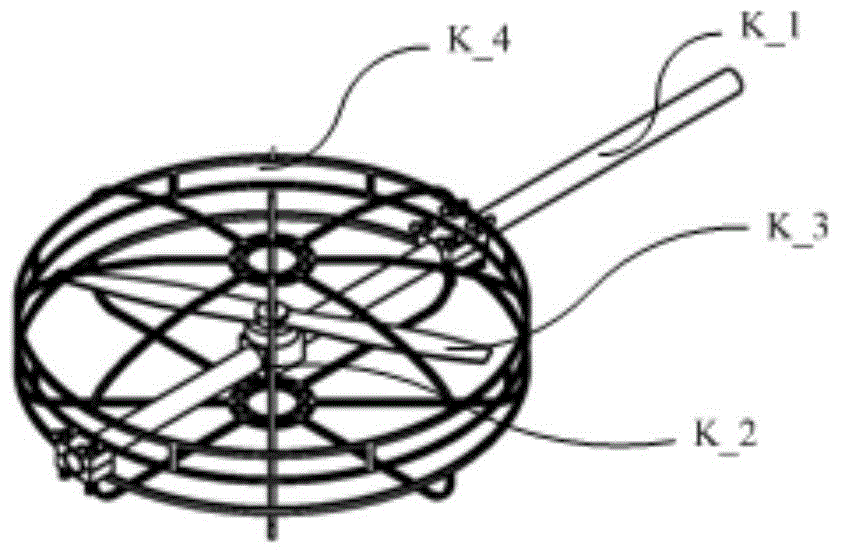
[0086] This embodiment is aimed at the disassembly and assembly design of the falling line traveling device.

[0087] The falling line walking device of this embodiment adopts the structure shown in Figure 3 (a)~(d), including: fixed support L_1, movable support L_2, moving wheel L_3, drive motor L_4, wheel support L_5, support wheel L_6, Guide fence L_7, auxiliary guide fence L_8 and guide camera L_9.

[0088] The bottom end of the fixed bracket L_1 is fixed on the top of the nacelle (not shown in Fig. 3(a)-(d)), and the top end of the fixed bracket L_1 is fixedly connected with the bottom end of the movable bracket L_2.

[0089] The moving wheel L_3, the driving motor L_4, the wheel support L_5, the support wheel L_6, the guide fence L_7 and the auxiliary guide fence L_8 are installed on the top of the movable support L_2. The driving motor L_4 is connected to the wheel shaft of the moving wheel L_3; the wheel bracket L_5 is vertically fixed on the top of the movable bracke...

Embodiment 3

[0096] This embodiment is designed for the disassembly and assembly of the inspection device.

[0097] The inspection device of this embodiment includes: a base, a pan-tilt, and an inspection camera. The base is fixedly connected to the bottom of the nacelle; the pan-tilt is fixed on the side of the base facing away from the nacelle, and the inspection camera is installed on the pan-tilt; Describe the shooting direction of the inspection camera.

[0098] In this embodiment, the fixed connection between the base and the bottom of the nacelle can be realized by bolts. For example, the bottom of the nacelle is provided with at least one downward lug, and the side of the base facing the nacelle is provided with at least one upward lug; The upper lugs match the upward lugs and are connected securely with bolts. That is, the base and the nacelle are disassembled and assembled through the bolt connection between these downward lugs and upward lugs. It should be noted that the lugs...


PUM


Abstract

The invention provides a multi-rotor-wing patrolling aircraft and a power transmission line patrolling system. The multi-rotor-wing patrolling aircraft comprises a multi-rotor-wing flight device, a line falling walking device, a patrolling device, a control device and a flight end wireless transmission interface, wherein the multi-rotor-wing flight device comprises a cabin, a plurality of rotor wings and an undercarriage; the line falling walking device comprises a support frame, a guide camera and a moving mechanism; the patrolling device comprises a patrolling camera; the flight end wireless transmission interface is wirelessly connected with a ground command device; the control device receives a command sent by the ground command device, controls the rotor wings to fly and controls the moving mechanism to move along a to-be-mounted conductive ground line. The power transmission line patrolling system comprises the multi-rotor-wing patrolling aircraft and the ground command device, wherein the ground command device particularly comprises an action command device, an image analyzing device, a display and a ground end wireless transmission interface. The power transmission line patrolling system has an accurate power line mounting function; the patrolling view field is widened; the patrolling efficiency is improved; the labor cost for patrolling is lowered.

Description

technical field [0001] The invention relates to the technical field of power transmission line inspection, in particular to a multi-rotor aircraft and a power transmission line inspection system. Background technique [0002] High-voltage and ultra-high-voltage overhead transmission lines are the main way to transmit electric energy over long distances. Ground wires and tower accessories have been exposed to the wild for a long time, and they are subject to continuous mechanical tension, electrical flashover, and material aging, resulting in broken strands, wear, and corrosion. If it is not repaired and replaced in time, the original small damage and defects may expand, eventually leading to serious accidents, causing large-scale power outages and huge economic losses. Therefore, the power company should regularly inspect the line equipment, find early damage and defects in time and evaluate them, and then arrange the necessary maintenance and repair at a reasonable cost and...

Claims


Application Information

Patent Timeline
Patent Type & Authority Applications(China)
IPC IPC(8): B64C27/08B64D47/08H02G1/02
Inventor 刘宏达张建斌蔡伟郭志广何红太李红云陈垚秦源汛裴冠荣王成曹向勇李红旗杨义清
Owner HENAN POWER TRANSMISSION & TRANSFORMATION CONSTR CO LTD
Why Eureka
Try Eureka