Eureka AIR delivers breakthrough ideas for toughest innovation challenges, trusted by R&D personnel around the world.

Device and method for producing synthetic gas by continuous two-stage catalytic pyrolysis

A catalytic pyrolysis and synthesis gas technology, applied in hydrogen/synthesis gas production, chemical instruments and methods, gasification catalysts, etc., can solve the problems of difficulty in processing, reduce the utilization characteristics of solid-phase products, and easily produce melting, etc., to achieve reduction Investment and secondary pollution, the effect of solving energy utilization and hazard problems

Inactive Publication Date: 2015-03-04
TSINGHUA UNIV
View PDF3 Cites 4 Cited by
  • Summary
  • Abstract
  • Description
  • Claims
  • Application Information

AI Technical Summary

Problems solved by technology

[0003] At present, there are still many problems and bottlenecks in the research of bio-oil refining. It still takes a certain distance to refine the pyrolysis liquid containing organic matter into real liquid petroleum for industrial application.
At the same time, the pyrolysis of biomass waste has relatively strict requirements on equipment, and at the same time, it is easy to produce a molten state during the high-temperature pyrolysis process, which will have a certain impact on the operation of equipment and working conditions.
At the same time, high-temperature pyrolysis will also easily reduce the utilization characteristics of solid-phase products, and the volatile products produced will contain more polluting substances such as heavy metals in sludge, making subsequent treatment difficult.

Method used


Image

  • Device and method for producing synthetic gas by continuous two-stage catalytic pyrolysis
  • Device and method for producing synthetic gas by continuous two-stage catalytic pyrolysis
  • Device and method for producing synthetic gas by continuous two-stage catalytic pyrolysis

Examples


Embodiment Construction

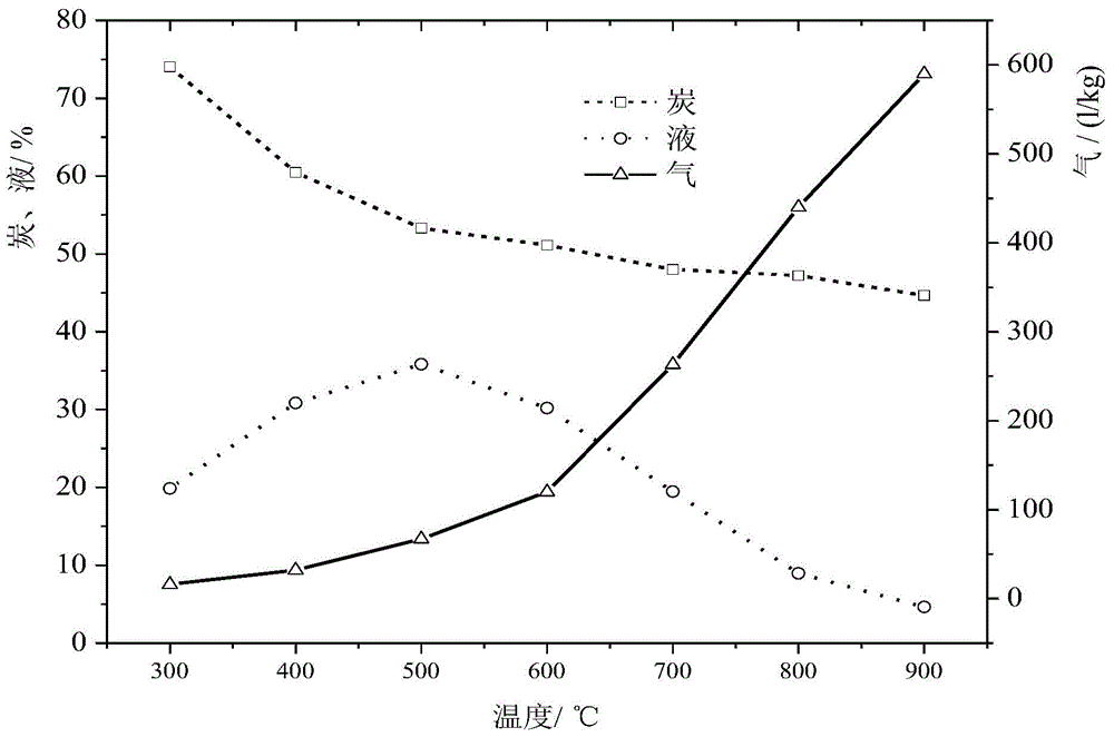
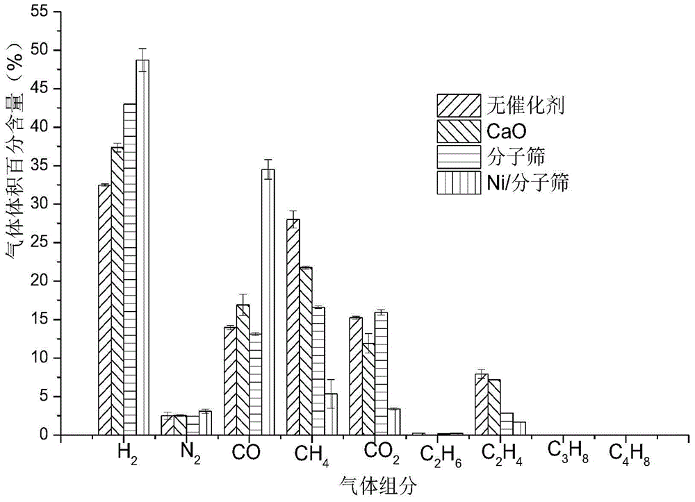
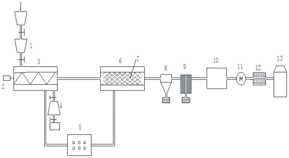
[0024] The present invention provides a continuous two-stage catalytic pyrolysis synthesis gas device and method. The specific technical method and device of the present invention will be described in detail and completely below in conjunction with the accompanying drawings and specific embodiments. The described specific implementation Ways are only some examples of the present invention, not all examples. All other examples obtained by those skilled in the art without creative efforts belong to the protection scope of the present invention.

[0025] A continuous two-stage catalytic pyrolysis synthesis gas production device, double-valve closed feeding device 1, a first-stage medium-temperature pyrolysis furnace 3, a second-stage high-temperature catalytic pyrolysis furnace 6, a gas-liquid separator 8, and a water condenser 9 , water washing box 10, induced draft fan 11, purifier 12 and gas storage tank 13 are connected in sequence; a section of medium-temperature pyrolysis f...


PUM


Abstract

The invention belongs to the technical field of energy utilization of reaction raw materials containing organic matters and particularly relates to a device and method for producing synthetic gas by continuous two-stage catalytic pyrolysis. The device comprises a double-valve airtight feeding device, a first-stage screw conveying motor, a first-section medium temperature pyrolysis furnace, a double-valve discharging device, a second-stage screw conveying motor, a second-section high temperature catalytic pyrolysis furnace, a catalyst module, a gas-liquid separator, a water condenser, a water scrubber, an induced draft fan, a purifier and a gas storage box. According to the method disclosed by the invention, the reaction raw materials containing the organic matters are converted into charcoal and crude fuel gas through medium temperature pyrolysis; then, the crude fuel gas is converted into the synthetic gas through high temperature catalytic reforming; therefore, the utilization and damage problems of pyrolysis liquid are solved and fuel gas purification investment and secondary pollution are reduced. Particularly, reforming reaction is generated among water, CO2 and organic matters generated during the pyrolysis of the reaction raw materials containing the organic matters to generate the synthetic gas, thereby solving the energy utilization and damage problems of pyrolysis liquid and reducing fuel gas purification investment and secondary pollution.

Description

technical field [0001] The invention belongs to the technical field of energy conversion of reaction raw materials containing organic matter, and in particular relates to a continuous two-stage catalytic pyrolysis device and method for producing synthesis gas. Background technique [0002] The organic matter in the reaction raw material containing organic matter is mainly converted into a liquid-phase fuel with certain energy during the low-medium temperature pyrolysis process, which is a complex mixture composed of hundreds of organic matter. The liquid fuel produced by pyrolysis has high oxygen content and high water content, and its calorific value is about 50% of that of petroleum products, and its stability is not good, so it is difficult to be directly used as fuel. At the same time, this kind of tar is an acidic viscous liquid substance. In actual engineering operation, it is easy to adhere to the inner wall of pipelines and equipment, causing pipeline blockage and eq...

Claims


Application Information

Patent Timeline
IPC IPC(8): C10B53/00C10B53/02C01B3/32
CPCC01B3/326C01B2203/06C10B53/00C10B53/02C10B57/00C10J3/62C10J3/66C10J3/84C10J2200/06C10J2300/0916C10J2300/0923C10J2300/0946C10J2300/0969C10J2300/0976C10J2300/1603C10J2300/1615Y02E50/10
Inventor 王凯军常风民林华汪翠萍
Owner TSINGHUA UNIV
Why Eureka
Eureka Blog
Learn More