Rocket time sequence controller and control method

A technology of timing controller and timing control circuit, applied in the direction of weapon types, projectiles, self-propelled projectiles, etc., can solve the problems of reduced reliability, insecurity, malfunction, etc., to ensure reliability and accuracy, and meet the general requirements. Improve design requirements and improve safety

Active Publication Date: 2015-03-04
中国航天科技集团公司第四研究院第四十一研究所
View PDF5 Cites 33 Cited by
  • Summary
  • Abstract
  • Description
  • Claims
  • Application Information

AI Technical Summary

Problems solved by technology

[0004] (1) No timing parameter setting function, unable to flexibly adapt to launch requirements
When the timing parameters need to be modified, the timing controller can only be disassembled and the timing controller program reprogrammed, and there is no test assessment after reprogramming the program, which reduces the reliability
[0005] (2) The counter adopts binary accumulative counting. If the main control chip is FPGA, during the accumulati

Method used


Image

  • Rocket time sequence controller and control method
  • Rocket time sequence controller and control method

Examples


Embodiment 1

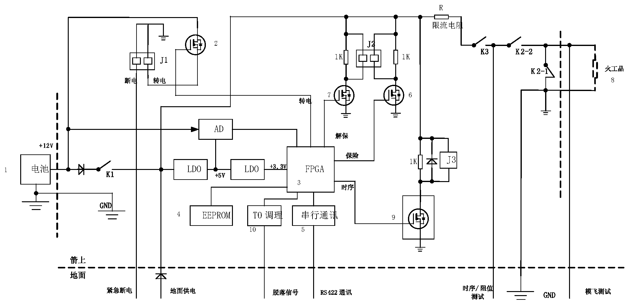
[0028] Embodiment 1, see attached figure 1 , rocket timing controller, which includes: power supply and distribution circuit, timing control circuit and ignition circuit;

[0029] The power supply and distribution circuit includes: the ground power supply circuit that supplies power to the rocket timing controller in time-sharing and the rocket battery 1; the two-stage voltage regulator that converts the 12V output from the ground power supply circuit and the rocket battery 1 into 5V and 3.3V Power supply LD0; convert the voltage of arrow-borne battery 1 into a digital quantity and provide it to the voltage detection circuit AD of the timing control circuit, and the voltage detection circuit AD receives the 5V voltage output from the two-stage regulated power supply LD0; the receiving and amplifying timing control circuit gives The first field effect tube 2 of the "power transfer" signal; the first two-way contact driven by the "power transfer" signal output by the first field...

Embodiment 2

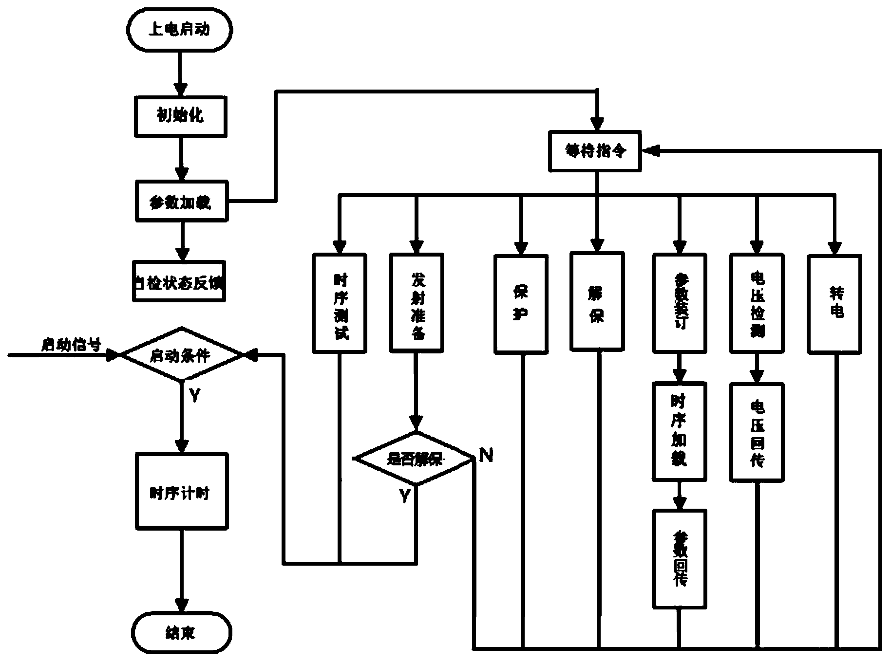
[0032] Embodiment 2, see attached figure 2 , a rocket timing control method, it uses the rocket timing controller as described in embodiment 1, and comprises the following steps:

[0033] A. After the rocket timing controller is powered on, load the timer inside the FPGA control chip 3 with the set timing parameters stored in EEPROM4; the feedback from the FPGA control chip 3 to the host computer includes the device model, serial number, batch, and status of the rocket timing controller information and the self-test information of the currently loaded set timing parameters;

[0034] B. The FPGA control chip 3 waits for and detects the ground control command from the serial communication interface 5; the ground control command includes "power transfer", "battery voltage detection", "timing parameter setting", "insurance", " Unlock", "Sequence Test" and "Launch Preparation", and the receiving of commands adopts the response mechanism;

[0035] C. After the FPGA control chip 3...


PUM


Abstract

The invention relates to a rocket control technology, in particular to time sequence control of a rocket. A rocket time sequence controller is characterized by comprising a power supply/distribution circuit, a time sequence control circuit and an ignition circuit; the controller adopts multiple safety protection measures; on hardware, the controller mainly depends on an initiating explosive device protection circuit to guarantee the safety of initiating explosive devices in the rocket storage, transportation and test process; the reliability of time sequence control output is improved by parallel connection of dual backups; on software, an even triggering mechanism is adopted, that is, when the time sequence controller receives a corresponding control instruction, the hardware can perform a corresponding action; after the performed action is correct, a state signal of finishing the action is returned; when a FPGA controls a flow, a corresponding state feedback signal is detected; and after the action is performed, a next action is performed. The rocket time sequence controller satisfies the resistance value testing and time sequence testing requirements of the initiating explosive devices before the rocket is launched, and guarantees the safety of the initiating explosive devices in the testing process.

Description

technical field [0001] The invention relates to rocket control technology, in particular to timing control of rockets. Background technique [0002] The timing control of small vehicles and uncontrolled rockets in my country is mainly realized by timers inside single-chip microcomputers or programmable logic devices (FPGA, CPLD, etc.). When using a single-chip microcomputer, a combination of a hardware timer and a software counter is often used; when a programmable logic device is used, a multi-bit counter is usually used. When the counting value of the counter is consistent with the set timing value, the timing signal is output to the driving circuit, and the driving circuit drives the distributor (mainly power supply and distribution and relay ignition circuit), and connects the ignition circuit of the pyrotechnic device. [0003] The previous timing controller design has the following deficiencies: [0004] (1) There is no timing parameter setting function, and it canno...

Claims


Application Information

Patent Timeline
IPC IPC(8): F42B15/01
Inventor 张拓刑广义彭勤素赵俊荣
Owner 中国航天科技集团公司第四研究院第四十一研究所
Why Eureka
Try Eureka