Dry gas recovery system and dry gas recovery method for refinery plant

A refinery dry gas and recovery system technology, which is applied in the processing of gas mixtures, the petroleum industry, and the treatment of hydrocarbon oil, can solve the problems of large investment, high energy consumption, and limited process applicability, so as to reduce energy consumption and Investment, energy consumption reduction, ideal absorption effect

Active Publication Date: 2015-03-18
CHINA PETROLEUM & CHEM CORP +1
View PDF8 Cites 11 Cited by
  • Summary
  • Abstract
  • Description
  • Claims
  • Application Information

AI Technical Summary

Problems solved by technology

[0011] In order to solve the problems of large investment, high energy consumption, and limited process applicability in the existing refiner

Method used


Image

  • Dry gas recovery system and dry gas recovery method for refinery plant

Examples


Embodiment

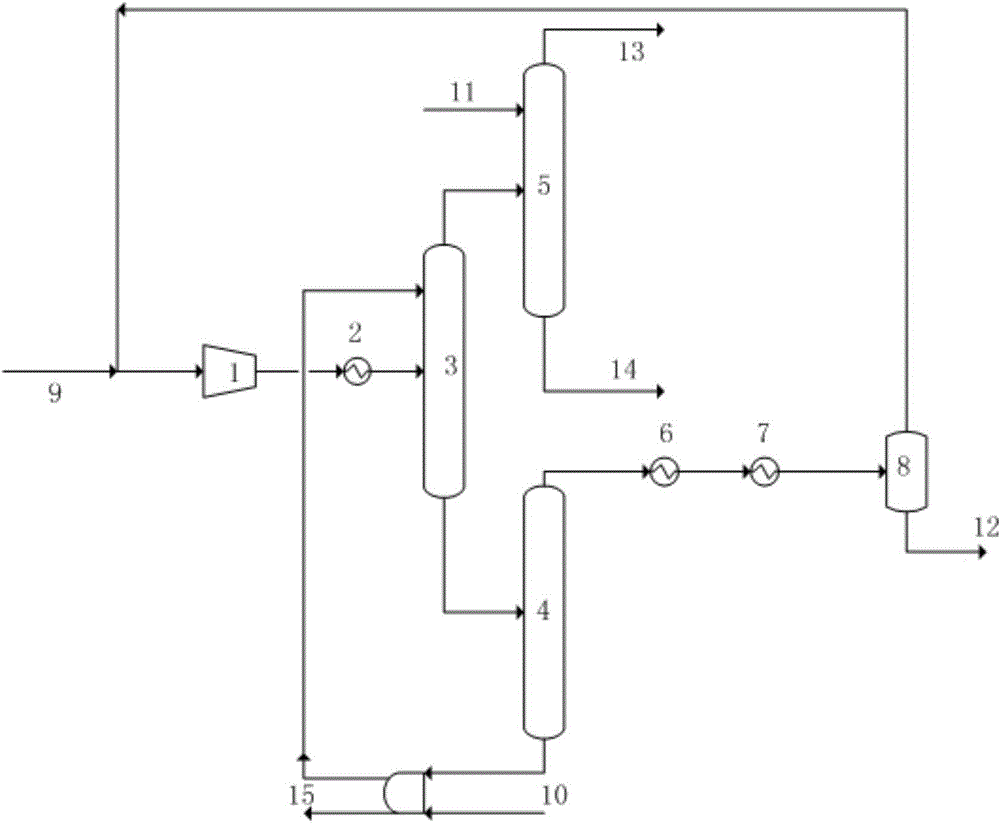
[0057] Such as figure 1 As shown, a refinery dry gas recovery system. Including: compressor 1, absorption tower 3, reabsorption tower 5, desorption tower 4, propylene refrigerant cooler 6, ethylene refrigerant cooler 7 and flash tank 8;

[0058] Compressor 1 is connected to heat exchanger 2 and then connected to absorption tower 3, the top of absorption tower 3 is connected to reabsorption tower 5, the bottom of absorption tower 3 is connected to desorption tower 4, and the top of desorption tower 4 is connected to propylene refrigerant cooler 6 and ethylene refrigerant cooling Device 7 and flash tank 8, the top of flash tank 8 is connected to the compressor 1 inlet; the absorption tower 2 is provided with an absorption tower still reboiler;

[0059] The dry gas composition is shown in Table 1,

[0060] Table 1

[0061] composition

[0062] The incoming material of refinery dry gas is 26700kg / h, and carbon four after ether is selected as the absorbent to recover e...


PUM


Abstract

The invention discloses a dry gas recovery system and method for a refinery plant. The system comprises a compressor, an absorption tower, a re-absorption tower, a stripping tower, a liquefying cooler and a flash tank, wherein the compressor is connected with a heat exchanger, and is then connected with the absorption tower; the top part of the absorption tower is connected with the re-absorption tower, and the bottom part of the absorption tower is connected with the stripping tower; the liquefying cooler and the flash tank are sequentially connected with the top part of the stripping tower; and the top part of the flash tank is connected with the inlet of the compressor. The method comprises the steps of compressing, cooling, absorbing, stripping and liquefying dry gas of the refinery plant to obtain carbon 2-enriched products. The method has the advantages of a little equipment, low energy consumption, simple flow and high recovery rate, and the product is easy to store and transport.

Description

technical field [0001] The invention relates to the field of refinery dry gas treatment, and more particularly, relates to a refinery dry gas recovery system and a dry gas recovery method. Background technique [0002] Refinery dry gas mainly comes from the secondary processing of crude oil, such as catalytic cracking, thermal cracking, delayed coking, hydrocracking, etc. Generally, the content of ethylene in catalytic dry gas is relatively high, while the content of ethane in coking dry gas is relatively high, about 15% to 25%. In addition, refinery dry gas also contains alkenes such as propylene, propane and butane. At present, most refineries in my country still burn the refinery dry gas as fuel gas, which has low utilization value and causes great waste of resources and environmental pollution. [0003] Ethane is an ideal raw material for cracking, and a considerable part of it is converted into ethylene during steam cracking. If the ethane in the refinery dry gas is r...

Claims


Application Information

Patent Timeline
IPC IPC(8): C10G70/04C10G70/06
CPCC10G70/04C10G70/06
Inventor 李东风李琰过良罗淑娟程建民廖丽华刘智信王婧
Owner CHINA PETROLEUM & CHEM CORP
Why Eureka
Try Eureka