Drying oven with double air channels for heat setting machine

A heat-setting machine and dual-air duct technology, used in textiles and papermaking, can solve problems such as uneven airflow, large air resistance, and affect the effect of heat-setting, to ensure the effect, uniform and smooth airflow, and reduce airflow resistance. Effect

Inactive Publication Date: 2015-03-18
WUXI CITY HUAYANG DYEING & FINISHING MACHINERY
0 Cites 0 Cited by

AI-Extracted Technical Summary

Problems solved by technology

The existing heat-setting machine oven uses a blower to directly blow hot air into the drying chamber to shape the fabric fibers. The disadv...

Method used

This shows that the advantage of the present invention is that the air outlet of blower fan is provided with deflector to be connected with hot-blast blowing device, and hot-blast blowing device has two, forms double air duct, is respectively positioned at the upper and lower sides of needle plate, makes air flow Uniform and smooth, reducing the airflow resistance and ensuring the heat setting effect. The invention adopts natural gas heating system, which has a fast heating speed, shortens the preparation time for heating up the oven, has low pollution, ...

Abstract

The invention discloses a drying oven with double air channels for a heat setting machine. The drying oven comprises a heat-insulation oven body and two hot-air blowing devices. The hot-air blowing devices are positioned in the heat-insulation oven body, a heat-insulation door is arranged on the heat-insulation oven body, the hot-air blowing devices are connected with a flow guide plate, the flow guide plate is connected with air outlets of a fan, air inlets of the fan are sequentially connected with a natural gas heating system, and the two hot-air blowing devices are respectively positioned above and below needle plates. The drying oven has the advantages that the flow guide plate is arranged at the air outlets of the fan and is connected with the hot-air blowing devices, the double air channels can be formed by the two hot-air blowing devices, the two hot-air blowing devices are respectively positioned above and below the needle plates, accordingly, airflow can uniformly smoothly flow, resistance on the airflow can be reduced, and heat setting effects can be guaranteed; the drying oven is provided with the natural gas heating system and is high in heating-up speed, the heating-up preparation time of the drying oven can be shortened, the drying oven is low in pollution and easy to maintain, the energy utilization rate of the drying oven can be maximized, accordingly, production requirements can be met, the production cost can be greatly reduced, integral production procedures are environmental friendly, and energy can be saved in the integral production procedures.

Application Domain

Technology Topic

Image

  • Drying oven with double air channels for heat setting machine

Examples

  • Experimental program(1)

Example Embodiment

[0008] The present invention will be further described below in conjunction with the accompanying drawings.
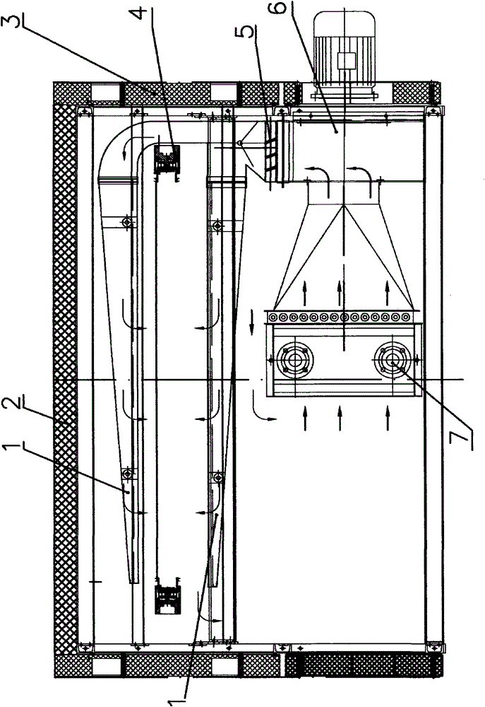
[0009] like figure 1 As shown, a double-channel heat setting machine oven of the present invention includes an insulated box 2 and a hot air blowing device 1 located in the insulated box 2, the insulated box 2 is provided with an insulated door 3, and the insulated box 2 is provided with a heat preservation door 3. The hot blast blowing device 1 is connected with the deflector 5, the deflector 5 is connected with the air outlet of the blower fan 6, the air inlet of the blower blower 6 is connected with the natural gas heating system 7 in sequence, and the hot blast blowing device 1 has two, They are respectively located above and below the needle plate 4.
[0010] When it is necessary to clean the hot air blowing device 1, open the heat preservation door 3 to easily clean up the sundries attached to the hot air blowing device 1. The hot air blowing device 1 is arranged in two, located above and below the needle plate 4 , set up like this and can evenly heat the fabric hanging on the needle plate 4, improve the quality of heat setting.
[0011] It can be seen that the advantage of the present invention is that the air outlet of the blower fan is provided with a deflector to be connected with the hot air blowing device, and there are two hot air blowing devices, forming double air passages, which are respectively located above and below the needle plate, so that the air flow is even and smooth, The airflow resistance is reduced, and the heat setting effect is guaranteed. The invention adopts a natural gas heating system, which has a fast heating speed, shortens the preparation time for the oven to heat up, has low pollution, and is easy to maintain. It maximizes the energy utilization rate of the oven, which not only meets the production needs, but also The production cost is greatly reduced, and the whole production process is more environmentally friendly and energy-saving.

PUM

no PUM

Description & Claims & Application Information

We can also present the details of the Description, Claims and Application information to help users get a comprehensive understanding of the technical details of the patent, such as background art, summary of invention, brief description of drawings, description of embodiments, and other original content. On the other hand, users can also determine the specific scope of protection of the technology through the list of claims; as well as understand the changes in the life cycle of the technology with the presentation of the patent timeline. Login to view more.

Similar technology patents

Classification and recommendation of technical efficacy words

  • Low air resistance

Light gas pipeline

InactiveCN101746378ALow air resistanceRun fastRailway tunnelsElectric propulsionGas pipelineProduct gas
Owner:彭智祥

Cyclone-type cycling filtration gas-water separation device for fuel cell system

PendingCN110289437ALow air resistanceGood gas permeabilityFuel cellsBeam tubeEngineering
Owner:武汉泰歌氢能汽车有限公司

Blade structure for centrifugal fans

InactiveCN102619783ALow air resistancePump componentsPumpsAgricultural engineeringAirflow
Owner:GUANGDONG CHIGO AIR CONDITIONING +2

Bicycle shift control device

InactiveUS20100037723A1Low air resistanceShaft for linear movementVariatorEngineering
Owner:TIEN HSIN INDS

Forced air cooling type heat dissipation case

PendingCN113747750ALow air resistanceImprove heat dissipation efficiency and heat dissipation effectModifications for power electronicsEngineeringForced air cooling
Owner:GUIYANG AVIATION MOTOR
Why Eureka
Try Eureka