
Automobile fuel-saving device capable of reducing fuel consumption through magnetic fields

A technology for automobiles and fuel consumption, applied in the direction of charging systems, engine components, machines/engines, etc., can solve the problems of loss, increase engine noise, engine energy waste, etc., achieve noise reduction, reduce exhaust emissions, and save fuel.

Inactive Publication Date: 2015-03-18
TIANJIN DAXINSHENG FUEL ECONOMIZING EQUIP TECH CO LTD
View PDF0 Cites 1 Cited by
  • Summary
  • Abstract
  • Description
  • Claims
  • Application Information

AI Technical Summary

Problems solved by technology

Among them, gasoline and diesel are commonly used. A fuel tank is installed on the frame of the car. The fuel in the fuel tank is transported to the engine through the gasoline pump and the oil pipe, and then after burning, the power generated drives the main shaft through the piston, and then the main shaft drives the car. Most of the heat generated by combustion is dissipated in the environment through the engine casing and exhaust gas. According to relevant statistics, most of the energy of the engine is wasted, which is related to various factors such as engine efficiency, fuel oil, and air quality. Molecular arrangement and large groups of oil and gas molecules will affect the efficiency of the engine and will increase the noise of the engine

Method used


Image

  • Automobile fuel-saving device capable of reducing fuel consumption through magnetic fields
  • Automobile fuel-saving device capable of reducing fuel consumption through magnetic fields

Examples


Embodiment Construction

[0013] Below in conjunction with the examples, the present invention is further described, the following examples are illustrative, not limiting, and the protection scope of the present invention cannot be limited by the following examples.

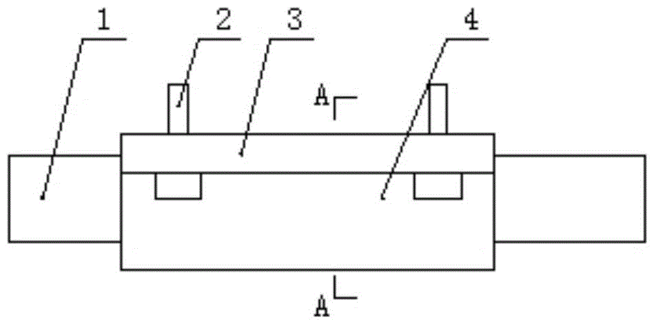
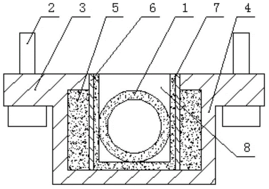
[0014] A car fuel-saving device that uses a magnetic field to reduce fuel consumption, such as figure 1 , 2 As shown, the innovation of the present invention is: comprise base 4 and strong magnet 5, make a groove 8 in the middle part of the base, be used for embedding automobile oil pipe 1 in this groove, a base side wall on both sides of this groove is installed Cover plate 6, strong magnets are all embedded in the base next to each cover plate, and a plurality of fixing bolts 2 are installed on the upper ends of both sides of the base.

[0015] In this embodiment, the upper ends of both sides of the base extend outward to form extension plates 3, and each extension plate is pierced with a plurality of upward bolts. A layer of elastic ...


PUM


Abstract

The invention relates to an automobile fuel-saving device capable of reducing fuel consumption through magnetic fields. The automobile fuel-saving device comprises a base and strong magnets. A groove is machined in the middle of the base, and an automobile fuel pipe is embedded into the groove; each of the positions, located on the two sides of the groove, of the side walls of the base is provided with a cover plate; the strong magnets are embedded into the positions beside the cover plates and in the base; and a plurality of fixing bolts are arranged at the upper ends of the two sides of the base. According to the invention, the groove where the fuel pipe is embedded is formed in the base, and each of the surfaces of the two sides of the groove is provided with one cover plate; the position, beside each cover plate, inside the base is provided with one strong magnet in an embedding manner; the opposite end faces of the two strong magnets are opposite in polarity, that is, the polarity of one end face is the N pole, and the polarity of the other end face is the S pole; and the cover plates and the bottom face of the groove are each provided with an elastic layer. The strong magnetic fields between the two strong magnets change the arrangement structure of fuel molecules in the fuel pipe, and therefore agglomerate fuel and gas molecules are separated more thoroughly, so that the noise of an engine is reduced by about 10 decibels, and the fuel oil is saved by 8 percent. Tail gas emissions are reduced, and the device is safe and reliable and does not damage a fuel path and a circuit of an original automobile.

Description

technical field [0001] The invention belongs to the technical field of automobile fuel saving, in particular to an automobile fuel saving device which utilizes a magnetic field to reduce fuel consumption. Background technique [0002] A car is a convenient means of transportation. It uses gasoline, diesel, natural gas, etc. as fuel, and burns in the engine to do work, thereby driving the car. Among them, gasoline and diesel are commonly used. A fuel tank is installed on the frame of the car. The fuel in the fuel tank is transported to the engine through the gasoline pump and the oil pipe, and then after burning, the power generated drives the main shaft through the piston, and then the main shaft drives the car. Most of the heat generated by combustion is lost in the environment through the engine casing and exhaust gas. According to relevant statistics, most of the energy of the engine is wasted, which is related to various factors such as engine efficiency, fuel oil, and a...

Claims


Application Information

Patent Timeline
IPC IPC(8): F02M27/04
Inventor 亢红杰
Owner TIANJIN DAXINSHENG FUEL ECONOMIZING EQUIP TECH CO LTD
Learn More