Method for making liquid ink gun, liquid ink gun and printing equipment

A liquid inkjet head and a manufacturing method technology, applied in the field of liquid inkjet head and printing equipment, liquid inkjet head manufacturing, can solve the problems of liquid ink backflow, affecting printing speed, reducing printing quality, etc., to improve accuracy, The effect of improving printing speed and printing accuracy, improving printing speed and printing quality

Active Publication Date: 2015-03-25
ZHUHAI SAILNER 3D TECH CO LTD
View PDF6 Cites 1 Cited by
  • Summary
  • Abstract
  • Description
  • Claims
  • Application Information

AI Technical Summary

Problems solved by technology

[0004] The invention provides a method for manufacturing a liquid inkjet head, a liquid inkjet head and a printing device, which are used to solve the problem that the existing liquid inkjet head easily causes the liquid ink to flow back to the ink supply hole and affect the printing speed, and can also avoid The problem of reduced print quality caused by the use of adhesives, and the mechanical strength of the pressure chamber can be improved

Method used


Image

  • Method for making liquid ink gun, liquid ink gun and printing equipment
  • Method for making liquid ink gun, liquid ink gun and printing equipment
  • Method for making liquid ink gun, liquid ink gun and printing equipment

Examples


Embodiment 1

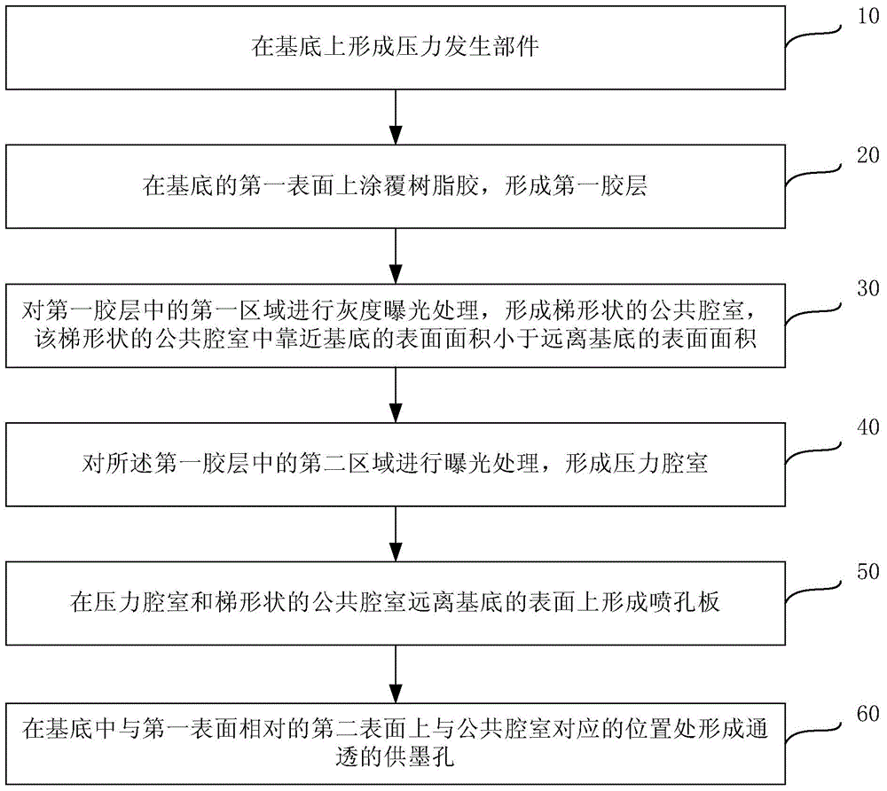
[0047] figure 1 It is a flow chart of the manufacturing method of the liquid inkjet head provided by Embodiment 1 of the present invention. Such as figure 1 As shown, the manufacturing method of the liquid inkjet head may include:

[0048] Step 10, forming a pressure generating component on the substrate.

[0049] Wherein, the substrate may be a silicon substrate or a glass substrate, and a silicon substrate is used in this embodiment. The function of the pressure generating part is to drive the ink in the pressure chamber to be ejected from the nozzle hole and printed on the printing medium, which can be various forms of devices, such as piezoelectric elements, thin film resistors, etc. In this embodiment, the piezoelectric element is taken as an example to specifically describe the method for forming the pressure generating member.

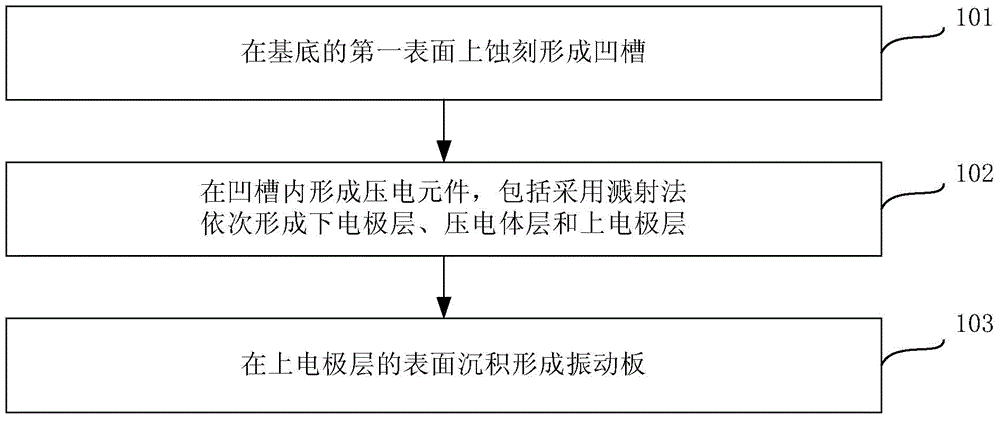
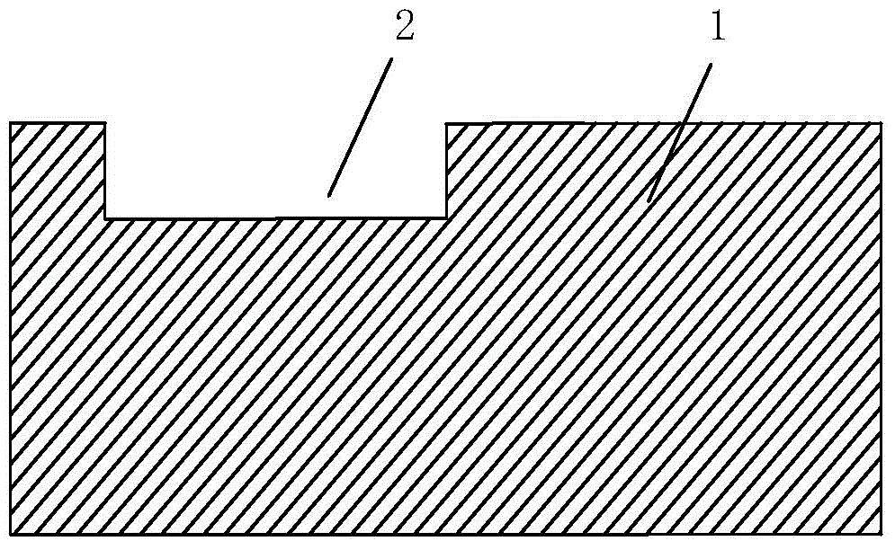
[0050] Specifically, refer to figure 2 , figure 2 It is a flowchart of a method for forming a pressure generating member in the method ...

Embodiment 2

[0101] This embodiment provides another method for forming a pressure generating component on the basis of the above embodiments, which may specifically include:

[0102] The vibrating plate 4 is formed by depositing on the first surface of the substrate 1 .

[0103] Specifically, it can be formed by low-pressure chemical vapor deposition or plasma-enhanced chemical vapor deposition, and the material of the vibrating plate 4 can be SiO 2 、Si 3 N 4 or SiO 2 -Si 3 N 4 stacks. This step can refer to Figure 10 , Figure 10 It is a schematic structural diagram of forming a vibrating plate on the surface of a substrate in the method for manufacturing a liquid inkjet head provided in Embodiment 2 of the present invention.

[0104] The piezoelectric element 3 is formed on the surface of the vibrating plate 4 away from the base 1 .

[0105] Specifically, the lower electrode layer can be formed by sputtering, the piezoelectric layer can be formed by sol-gel method, and the upp...

Embodiment 3

[0108] This embodiment provides yet another method for forming a pressure generating component on the basis of the above embodiments, which specifically includes:

[0109] A thin film resistance layer 19 is deposited on the first surface of the substrate 1 .

[0110] Specifically, the thin film resistance layer 19 can be deposited on the substrate 1 , and the material of the thin film resistance layer 19 can be one of tantalum aluminum alloy, nickel cadmium alloy, tungsten silicon nitride and titanium nitride. Can refer to Figure 13 , Figure 13 It is a schematic structural diagram of forming a thin-film resistance layer on a substrate in the method for manufacturing a liquid inkjet head provided in Embodiment 3 of the present invention.

[0111] For the forming method of other components in the liquid inkjet head, reference may be made to the technical solutions provided in the above embodiments, and details will not be repeated here. The formed liquid inkjet head structu...


PUM


Abstract

The invention provides a method for making a liquid ink gun, the liquid ink gun and printing equipment. The method comprises the steps that a pressure generating component is formed on a base; the first surface of the base is coated with resin adhesives, and a first adhesive layer is formed; gray exposure treatment is carried out on the first area in the first adhesive layer, and a trapezoidal common chamber is formed; exposure treatment is carried out on the second area in the first adhesive layer, and a pressure chamber is formed; spray hole plates are formed on the surfaces, away from the base, of the pressure chamber and the trapezoidal common chamber; a through ink supply hole is formed in the position, corresponding to the common chamber, of the second surface, opposite to the first surface, of the base. According to the method for making the liquid ink gun, the liquid ink gun and the printing equipment, the problem that according to an existing liquid ink gun, liquid ink is prone to flowing back to the ink supply hole, and printing speed is influenced can be solved, the problem that printing quality is lowered due to the fact that adhesives are adopted can be avoided, and the mechanical strength of the pressure chamber can be improved.

Description

technical field [0001] The invention relates to printer manufacturing technology, in particular to a method for manufacturing a liquid inkjet head, a liquid inkjet head and printing equipment. Background technique [0002] Printer is a commonly used office equipment. With the gradual advancement of printer technology, the speed of file processing and printing is getting more and more attention. In the prior art, the structure of the liquid inkjet head of the printer usually includes a substrate made of silicon material, an orifice plate bonded on the first surface of the substrate, and an orifice plate arranged on the second surface of the substrate opposite to the first surface. Vibration plate and piezoelectric element. The processing method of the liquid inkjet head is usually: forming a vibrating plate and a piezoelectric element on the second surface of the substrate, using an etching process to form a plurality of pressure chambers corresponding to the positions of th...

Claims


Application Information

Patent Timeline
Patent Type & Authority Applications(China)
IPC IPC(8): B41J2/16
Inventor 李越
Owner ZHUHAI SAILNER 3D TECH CO LTD
Why Eureka
Try Eureka