
Furnace

A heating furnace and optical fiber technology, which is applied in glass manufacturing equipment, instruments, glass fiber drawing devices, etc., can solve problems such as adhesion, carbon fiber falling off of brushes, and fiber strength reduction.

Inactive Publication Date: 2015-03-25
SHIN ETSU CHEM CO LTD
View PDF6 Cites 3 Cited by
  • Summary
  • Abstract
  • Description
  • Claims
  • Application Information

AI Technical Summary

Problems solved by technology

[0018] However, the carbon fibers that form the brushes can fall off and stick to the surface of the glass preform
As a result, the strength of the fiber may decrease

Method used


Image

  • Furnace
  • Furnace
  • Furnace

Examples


Embodiment 1

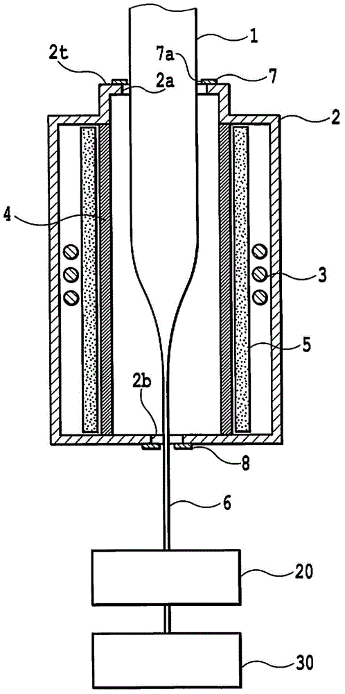
[0049] By using such as Figure 4 The shown heating furnace 2 heats ten glass preforms 1 having an average outer diameter of 64 mm, outer diameter fluctuations within ±2 mm, and a length of 1000 mm, and draws wires from the heated and melted ends of the glass preforms 1 optical fiber.

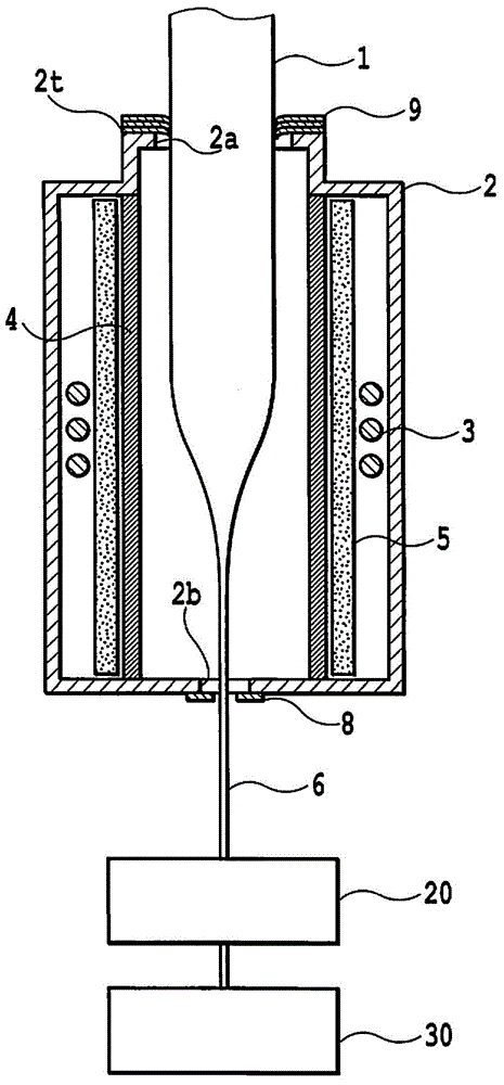
[0050] At the preform insertion port 2a of the heating furnace 2, ring-shaped sealing bodies produced under the following conditions were stacked.

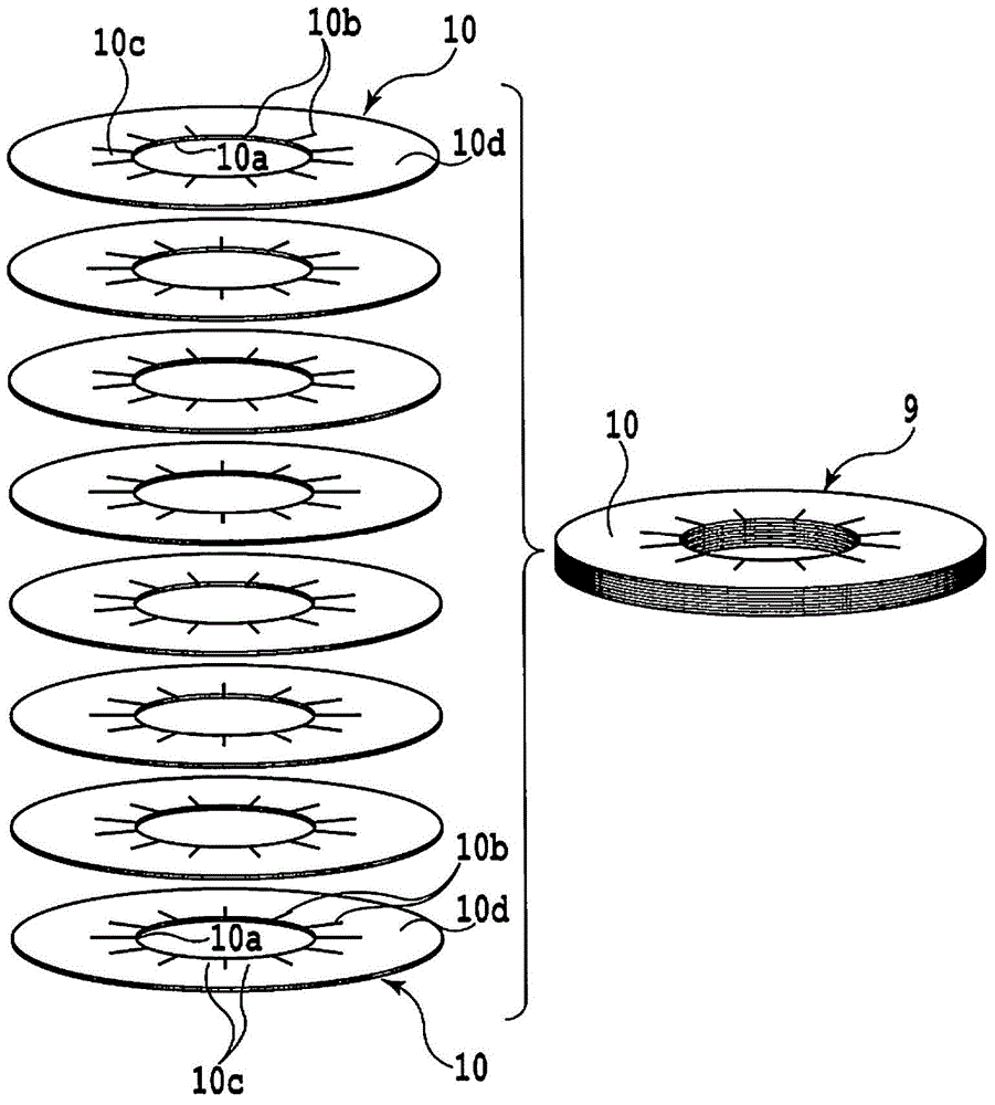
[0051] The annular disk 10 is made of a highly oriented pyrolytic graphite sheet with a thickness of 0.1 mm, and its insertion hole 10 a has a diameter of 60 mm. Twelve slits 10b having a length of 20 mm are formed in the annular disk 10 such that they extend radially from the inner edge of the insertion hole 10a of the annular disk 10 at angular intervals of 30° in the circumferential direction.

[0052] The annular sealing body 9 is formed by stacking eight annular disks 10 with the same structure, so that the adjacent annular disks are misalig...


PUM


Abstract

The present invention provides a furnace which is used for fabricating glass preform or an optical fiber. The furnace for heating an optical fiber preform to be inserted from an insertion opening, the furnace includes an annular sealing body for sealing a clearance gap between the optical fiber preform and the insertion opening. The annular sealing body is formed from stacked annular disks respectively having an insertion hole in its center area. The annular disk has slits formed from a inner edge of the annular disk toward its periphery side and flexible portions that are defined by the slits and bend by an interference with the optical fiber preform to be inserted into the insertion hole. When the optical fiber preform is inserted into the insertion hole of the annular sealing body, the flexible portions bend.

Description

[0001] This application is a divisional application of the invention application filed by the applicant Shin-Etsu Chemical Industry Co., Ltd. on July 24, 2008, the application number is 200810129961.7, and the invention name is "heating furnace". technical field [0002] The present invention relates to a heating furnace used in a sintering process for transparent vitrification of a porous glass preform, a drawing process for reducing the diameter of a glass preform and The preform is heated in a process for making optical fibers from the glass preform. Background technique [0003] Optical fibers are manufactured through several processes. First, a process of depositing glass particles as a raw material on a mandrel is performed to manufacture a porous glass preform. Then, the porous glass preform is heated to sinter the preform and produce a transparent vitrified glass preform. Then, heating and drawing of the glass preform are performed to reduce its outer diameter to m...

Claims


Application Information

Patent Timeline
Patent Type & Authority Applications(China)
IPC IPC(8): C03B37/01C03B37/029G02B6/00
CPCC03B37/029C03B37/091C03B2205/64C03B2205/80Y02P40/57
Inventor 乙坂哲也
Owner SHIN ETSU CHEM CO LTD
Features
  • Generate Ideas
  • Intellectual Property
  • Life Sciences
  • Materials
  • Tech Scout
  • Unparalleled Data Quality
  • Higher Quality Content
  • 60% Fewer Hallucinations
Learn More