Nucleic acid extractor

A nucleic acid extractor and nucleic acid technology, applied in biochemical instruments, biochemical equipment and methods, DNA preparation, etc., can solve the problem that it is difficult to meet the needs of high-throughput sample extraction and purification, the single magnetic bead movement function of the extraction device, and limited detection Flux and other issues, to achieve high yield, low cost, high extraction purity

Active Publication Date: 2015-03-25
JIAXING QUEST LIFE SCI
8 Cites 25 Cited by

AI-Extracted Technical Summary

Problems solved by technology

However, it is quite difficult to purify samples manually. Not only does it need to choose a suitable purification technology, but also the workload is particularly large and the repeatability is poor.
It is difficult to meet the current rapid development of extraction and purification of high-throughput samples
At present, most inspection institutions adopt the method of manual experimental operation and semi-...

Method used

In the present embodiment, described elevating mechanism 54 comprises first screw rod 541 and nut 542, and described third motor 52 output end is provided with driving wheel 543, and described first screw rod 541 upper end is provided with driven wheel 544 and Two upper bearings 545, the driven wheel 544 is connected with the driving wheel 543 through the third synchronous belt 546, the lower end of the first screw 541 is provided with a lower bearing 547, and the upper bearing 545 passes through the upper bearing frame 548 is fixed and locked with the first lock nut 549, the lower bearing 547 is fixed by the lower bearing frame 5410, the nut 542 is sleeved on the upper middle part of the first screw rod 541, and is located inside the fixed block 533 , fixed by nut gland 5411. The up and down movement of the gun head assembly 53 is realized through the mutual cooperation of the first screw rod 541 and the nut 542. This kind of movement is relatively stable, thereby ensuring the accuracy of loading the conductive suction tip 538 and making the loading more in place.
In the present embodiment, described sample chamber 4 is positioned at the right side of described table top 7, and nucleic acid extraction module 3 is located at the middle rear part of described table top 7, and described reagent area 17 is located at described nucleic acid extraction module 3 On the left side of the platform 7, there is a tip area located in front of the nucleic acid extraction module 3 and the reagent area 17, and a nucleic acid placement area 11 is located between the tip area and the sample chamber 4. The above layout setting conforms to the movement trajectory of the row gun module 5 and the single gun module 6, and can prevent cross-contamination to the greatest extent. The setting of the nucleic acid storage area 11 is convenient for the user to store the sample after the nucleic acid is extracted, which is convenient for the next step test.
In the present embodiment, described sample warehouse 4 comprises base plate 41, three sample racks 42, sample rack fence 43, flap door 44 and droplet protection plate 45, and described sample rack fence 43 is three side fences, and is provided with On the upper surface of the bottom plate 41, the flip door 44 is located at the opening of the sample rack fence 43, and is rotatably connected with the bottom plate 42, and the sample rack 42 is inserted into the sample from the opening of the sample rack fence 43. Inside the rack fence 43 , the droplet protection plate 45 is arranged above the sample rack 42 and mounted on the sample rack fence 43 . Place the sample rack 42 in the sample rack fence 43, and cover the droplet protection plate 45 above the sample rack 42 to effectively prevent sample contamination, and the setting of the flap door 44 is convenient for users to take and place the sample rack 42.
In the present embodiment, described sliding mechanism 55 comprises first guide rail 551 and slide bloc...

Abstract

The invention relates to the technical field of medical equipment and particularly relates to a nucleic acid extractor. The nucleic acid extractor comprises a shell, a rack, a nucleic acid extracting module, a sample bin, a reagent region, a multi-pipette module and a single-pipette module, wherein a table board is arranged on the rack; the nucleic acid extracting module, the sample bin and the reagent region are arranged on the table board; the multi-pipette module and the single-pipette module are positioned above the table board; an X arm is arranged on the rack; a multi-pipette Y arm and a single-pipette Y arm are arranged on the X arm; the multi-pipette Y arm and the single-pipette Y arm slide along the X arm; the multi-pipette module is arranged on the multi-pipette Y arm and slides along the multi-pipette Y arm; the single-pipette module is arranged on the single-pipette Y arm and slides along the single-pipette Y arm. The invention provides the nucleic acid extractor which is simple in structure, capable of preventing cross contamination and small in difference.

Application Domain

Technology Topic

ChemistryPipette +3

Image

  • Nucleic acid extractor
  • Nucleic acid extractor
  • Nucleic acid extractor

Examples

  • Experimental program(1)

Example Embodiment

[0060] Below in conjunction with accompanying drawing and embodiment the present invention is described in further detail:
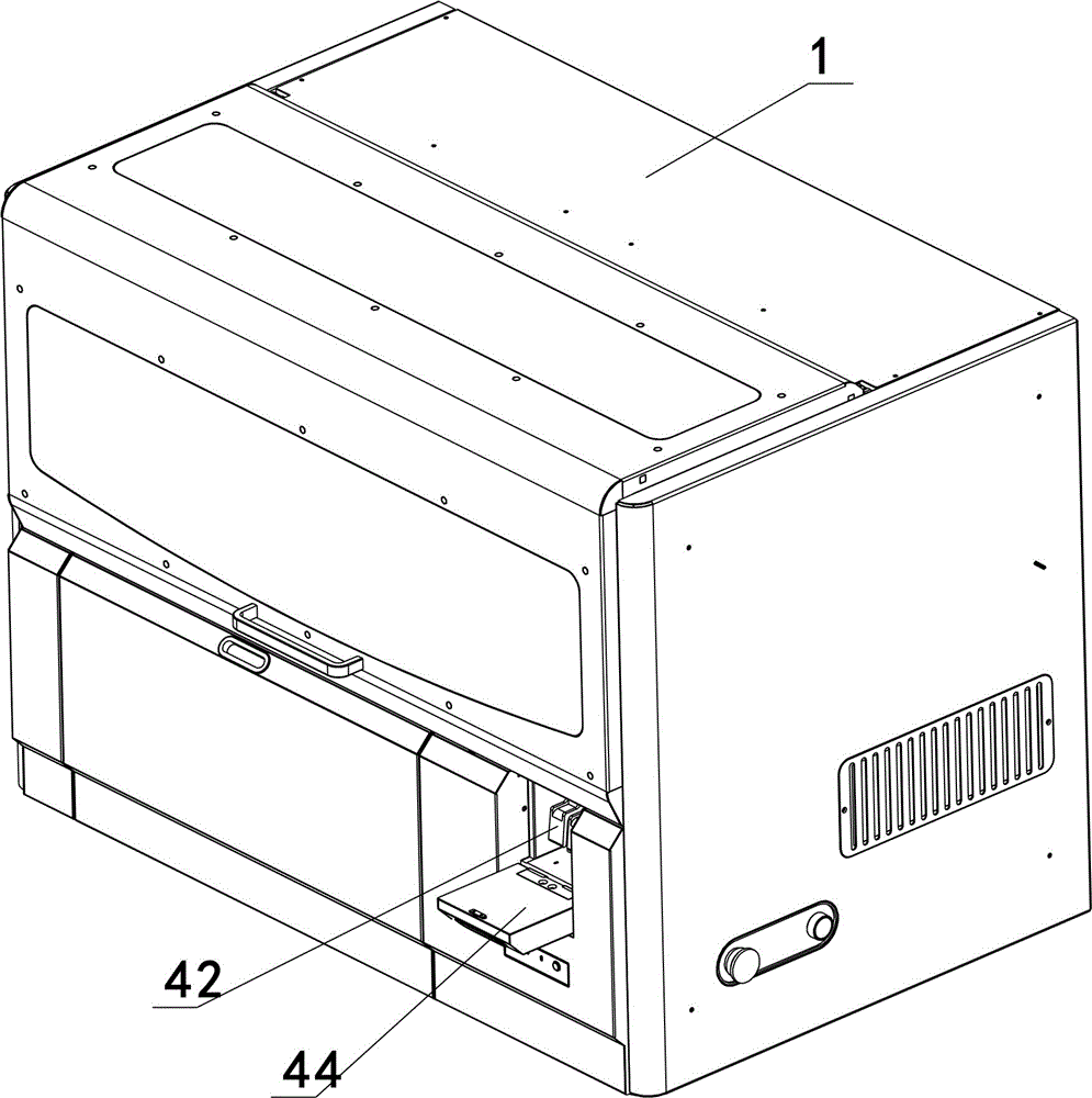
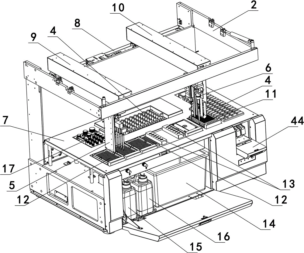
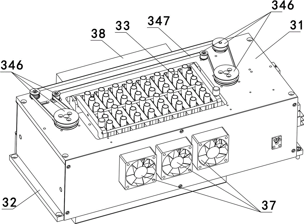
[0061] As an embodiment of the nucleic acid extractor of the present invention, such as figure 1 , figure 2 , image 3 , Figure 4 , Figure 5 , Image 6 , Figure 7 , Figure 8 , Figure 9 , Figure 10 , Figure 11 , Figure 12 , Figure 13 , Figure 14 , Figure 15 , Figure 16 , Figure 17 , Figure 18 , Figure 19 and Figure 20 As shown, it includes a shell 1, a frame 2, a nucleic acid extraction module 3, a sample chamber 4, a reagent area 17, a row gun module 5 and a single gun module 6, the rack is provided with a table 7, and the nucleic acid extraction module 3, The sample chamber 4 and the reagent area 17 are all arranged on the table top 7, the gun module 5 and the single gun module 6 are located above the table top 7, the frame 2 is provided with an X arm 8, and the X arm 8 is provided with a There are a platoon gun Y arm 9 and a single gun Y arm 10, the platoon gun Y arm 9 and the single gun Y arm 10 slide along the X arm 8, the platoon gun module 5 is arranged on the platoon gun Y arm 9, and slides along the platoon gun Y arm 9. 9 sliding, the single gun module 6 is arranged on the single gun Y arm 10 and slides along the single gun Y arm 10. The single gun module 6 is used to add samples, transfer samples and add cleaning fluid, the row gun module 5 is used to extract the waste liquid in the exhaust pipe, the X arm 8, the row gun Y arm 9 and the single gun Y arm The setting of 10 can make the row gun module 5 and the single gun module 6 move arbitrarily on the horizontal plane, so as to realize the anti-pollution movement, ensure that the sample will not be polluted, and the operations such as adding cleaning liquid and extracting waste liquid will not pollute the sample, ensuring The accuracy and purity of nucleic acid extraction are guaranteed.
[0062] In this embodiment, the nucleic acid extraction module 3 includes a housing 31, a base 32, a row pipe 33, a vibration mechanism 34, a heating mechanism 35 and a magnetic adsorption mechanism 36, and the row pipe includes six reaction tubes connected together, The heating mechanism 35 is arranged on the upper surface of the base 32, the exhaust pipe 33 is arranged on the vibrating mechanism 34, the vibrating mechanism 34 is located above the heating mechanism 35, and the magnetic adsorption mechanism 36 is located Between the heating mechanism 35 and the vibrating mechanism 34, and move along the upper surface of the heating mechanism 35, the housing 31 is arranged above the base 32 and is located between the vibrating mechanism 34, the heating mechanism 35 and the magnet. The adsorption mechanism 36 is external. The high-efficiency vibration efficiency of the vibration mechanism 34 improves the extraction efficiency, the heating mechanism 35 realizes the heating function, and makes the samples in the row tube 33 perform an incubation operation, and the magnetic adsorption mechanism 36 attracts the samples in the row tube 33 by magnetic force. Magnetic particles, and then the rest of the liquid in the discharge pipe 33 is drawn out of the discharge pipe 33 through the discharge gun module 5, and cleaned several times.
[0063] In this embodiment, the vibrating mechanism 34 includes a vibrating plate 341, a first motor 342, two eccentric shafts 343 and two pressing blocks 344, the exhaust tube 33 is arranged on the vibrating plate 341, and the first The motor 342 is arranged on the base 32, and two eccentric shafts 343 are respectively arranged on the two ends of the vibrating plate 341. The eccentric shaft 343 is sleeved with a bearing 345, and is pressed by a pressing block 344. The eccentric Both the upper end of the shaft 343 and the output end of the first motor 342 are provided with a first synchronous pulley 346 , and the two eccentric shafts 343 are connected with the first motor 342 through a first synchronous belt 347 . The first motor 342 is used to drive the eccentric shaft 343 to rotate to realize the vibration of the vibrating plate 341 back and forth on the horizontal plane, which can fully shake the liquid in the discharge pipe 33. Two eccentric shafts 343 are used to ensure the level of the vibrating plate 341 when vibrating. To prevent the liquid in the discharge pipe 33 from splashing out, thereby reducing the possibility of cross-contamination.
[0064]In this embodiment, the heating mechanism 35 includes a first linear motor 351, a heating plate 352 and a heating sheet 353. The heating sheet 353 is arranged below the heating plate 352 and is pressed by a pressing plate 354. The heating A heat shield 355 is provided on the upper surface of the plate 352, a first guide rod 356 is provided at both ends of the heating plate 352 downward, a screw rod 357 is provided downward at the middle of the heating plate 352, and two first guide rods 356 are provided downward. The lower end of a guide rod 356 passes through the base 32, the first linear motor 351 is arranged on the lower surface of the base 32, the lower end of the screw rod 357 passes through the base 32, and is aligned with the first linear motor. The motors 351 are connected, and forty-eight heating holes 358 are arranged on the heating plate 352. The forty-eight heating holes 358 are arranged in six rows and eight columns. Forty-eight through holes 359 are provided, and a layer of thermal insulation cotton 360 is provided outside the heating plate 352 and the heating sheet 353 . The heating sheet 353 adopts resistance heating to transfer heat to the heating plate 352. In the heated state, the lower end of the row pipe 33 sinks into the heating hole 358, so the heat generated by the heating sheet 353 is transferred to the row pipe 33 The liquid inside is further realized to incubate; the thermal insulation cotton 360 plays the role of heat preservation and prevents the heat generated by the heating sheet 353 from being lost.
[0065] In this embodiment, the magnetic adsorption mechanism 36 includes a magnetic steel base 361, a magnetic steel 362, and a second motor 363, and the magnetic steel base 361 is provided with twenty-one magnetic steel installation slots 364, and twenty-one magnetic steel mounting grooves 364 are provided. The steel mounting grooves 364 are arranged in three rows and seven columns. The magnetic steel 362 is arranged in the magnetic steel mounting grooves 364 and pressed tightly by the magnetic steel cover 365. The magnetic steel cover 365 is connected with the magnetic steel cover 365 by screws 366 The magnetic steel base 361 is connected, and two guide rods 367 parallel to each other are arranged between the two corresponding inner surfaces of the housing 31, and the magnetic steel base 361 is set on the two guide rods 367 , the second motor 363 is arranged on the inner surface of the housing 31, and is connected with the magnetic steel base 362 through a second timing belt 368, and the second timing belt 368 is passed through a timing belt pressing piece 369 It is connected with the magnetic steel seat 361. After the cooling is completed, the operation of the second motor 363 drives the magnetic adsorption mechanism 36 to move to the left for magnetic adsorption, and moves a position every one minute, so as to ensure that no single reaction tube of each exhaust pipe 33 is subjected to a three-minute reaction. Magnetic adsorption operation, the design and movement of the above magnetic adsorption mechanism 36 make the adsorption time of each row pipe 33 consistent, avoiding the influence of the difference in the adsorption time length on the result; after three minutes, the waste liquid is pumped, and then every Pump every minute.
[0066] In this embodiment, a set of blowing fans 37 and a set of suction fans 38 are respectively provided on two corresponding sides of the housing 31 , and the blowing fans 37 and the suction fans 38 are arranged symmetrically to each other. The arrangement of the blowing fan 37 and the suction fan 38 facilitates the discharge of heat inside the casing 31 .
[0067] In this embodiment, the lance module 5 includes a lance backboard 51, a third motor 52, a lance head assembly 53, a lifting mechanism 54 and a sliding mechanism 55, and the lance backboard 51 is fixed on the Y arm 9 of the lance, The third motor 52 is arranged on the top of the platoon gun backboard 51 and is connected with the lifting mechanism 54. The platoon gun head assembly 53 is slidably connected with the platoon gun backboard 51 through a sliding mechanism 55, and is lifted by lifting Mechanism 54 realizes sliding up and down. The function of the discharge gun module 5 is to extract the waste liquid used for cleaning the magnetic beads in the discharge pipe 33 out of the discharge pipe, and perform multiple extractions.
[0068] In this embodiment, correspondingly, the gun head assembly 53 includes six gun heads 531, a gun head frame 532, a fixed block 533 and a gun buffer mechanism 534, and the gun head 531 is vertically arranged on the gun head frame 532 Above, the middle part of the gun head 531 is covered with a sliding sleeve 535 and a first compression spring 536, the first compression spring 536 is located above the sliding sleeve 535, and the upper end of the gun head 531 is covered with a joint 537, The upper end is covered with a non-conductive suction head 538; the gun head holder 532 is connected to the fixed block 533 through a gun head block 539, and the gun buffer mechanism 534 includes a second guide rod 5341 and a second compression spring 5342, The upper end of the second guide rod 5341 is connected to the fixed block 533, and the lower end is inserted into the gun head block 539. The lower end of the second guide rod 5341 is provided with a first linear bearing 5343. A linear bearing 5343 is located between the second guide rod 5341 and the gun head block 539, the second compression spring 5342 is sheathed on the second guide rod 5341, and is located on the first straight line. Line bearing 5343 above. Each gun head 531 on the gun assembly 53 can move up and down independently. When the gun head 531 moves downward to load the non-conductive suction head 538, the loading force of the six gun heads 531 is ensured to be similar. There will be no situation that individual gun heads 531 fail to load non-conductive suction heads 538, and it can also avoid that individual non-conductive suction heads 538 are not loaded firmly enough due to different loading forces. 538 drop cases.
[0069] In this embodiment, the lifting mechanism 54 includes a first screw 541 and a nut 542, the output end of the third motor 52 is provided with a driving wheel 543, and the upper end of the first screw 541 is provided with a driven wheel 544 and two upper Bearing 545, the driven wheel 544 is connected with the driving wheel 543 through the third synchronous belt 546, the lower end of the first screw 541 is provided with a lower bearing 547, and the upper bearing 545 is fixed by the upper bearing frame 548, And locked with the first locking nut 549, the lower bearing 547 is fixed by the lower bearing frame 5410, the nut 542 is sleeved on the upper middle part of the first screw rod 541, and is located inside the fixed block 533, through the nut Gland 5411 is fixed. The up and down movement of the gun head assembly 53 is realized through the mutual cooperation of the first screw rod 541 and the nut 542. This kind of movement is relatively stable, thereby ensuring the accuracy of loading the conductive suction tip 538 and making the loading more in place.
[0070] In this embodiment, the sliding mechanism 55 includes a first guide rail 551 and a slider 552, the first guide rail 551 is vertically arranged on the back plate 51 of the row gun, and the slider 552 is arranged on the fixed block 533 Above, the slider 552 is locked on the first guide rail 551 and slides up and down along the first guide rail 551 . The first guide rail 551 and the slider 552 ensure the verticality of the vertical movement of the gun head assembly 53, thereby ensuring the accuracy of loading the conductive suction head 538 and making the loading more in place.
[0071] In this embodiment, the single gun module 6 includes a single gun back plate 620, a single gun adapter block 61, a single gun head 62, a piston 63, a cylinder 64, a second linear motor 65, a first circuit board 66 and a Liquid mechanism 621, the liquid adding structure 621 includes a fourth motor 6211, a liquid adding needle 6212 and a third linear motor 6213, the fourth motor 6211 drives the single gun adapter block 61 to move up and down through the fourth synchronous belt 6214 , the third linear motor 6213 drives the liquid filling needle 6212 to move up and down; the single gun back plate 620 is fixed on the single gun Y arm 10, and the output end of the second linear motor 65 passes through the piston adapter block 67 Connected with the upper end of the piston 63, the lower end of the piston 63 is located inside the cylinder body 64, the upper end of the single gun head 62 is connected with the lower end of the cylinder body 64 through an insulating connecting column 68, and is connected with the cylinder body 64 lower end. The cylinder body 64 is internally connected, the cylinder body 64 is provided with an air pressure joint 69, the air pressure joint 69 communicates with the cylinder body 64, and the first circuit board 66 is provided with an air pressure joint 69 connected with A common air pressure sensor 610, the single gun head 62 is provided with a conductive block 611 connected to the first circuit board 66, the second linear motor 65 is electrically connected to the first circuit board 66, and the single gun head 62 The lower end is provided with a conductive suction head 612 . The single gun head 62 of the single gun module 6 is used to transfer the sample in the sample chamber 4 to the discharge pipe 33, and transfer the sample after the nucleic acid is extracted to the nucleic acid placement area 11, and the liquid adding structure 621 is used for Add cleaning solution in drain pipe 33. The air pressure sensor 610 can be used to detect the liquid level. When the single gun head 62 starts to move downward, the piston 63 is located at the upper end of the cylinder 64. As the single gun head 62 moves downward, the piston 63 simultaneously Moving downward, the gas in the cylinder body 64 is slowly discharged from the lower end of the single gun head 62. When the lower end of the single gun head 62 touches the liquid surface, the gas in the cylinder body 64 cannot be removed temporarily. Then cause the air pressure in the cylinder body 64 to rise, then the air pressure sensor 610 detects the air pressure signal that rises suddenly, it can be known that the single gun head 62 has touched the liquid surface, and the first circuit board 66 records the height position of the single gun head 62, The liquid includes samples, reagents, etc.; the air pressure sensor 610 can also be used to detect whether the liquid leaks after the liquid is absorbed in the suction head. When the liquid leaks, the air pressure in the cylinder will suddenly increase. If the air pressure sensor 610 detects a sudden drop in the air pressure signal, it can be known that there is a liquid leakage, which is convenient for the user to perform remedial operations in time. When the conductive suction head 612 and the conductive block 611 generate a voltage signal when the conductive suction head 612 touches the liquid surface, it can be seen that the single gun head 62 has touched the liquid surface, and the first circuit board 66 records the temperature of the single gun head 62. At the height position, first rise and then descend for the operation of absorbing liquid. According to different detection items, the air pressure sensor 610 can be selected to detect the liquid level or the conductive block 611 can be used to detect the liquid level.
[0072] In this embodiment, the single gun module 6 also includes two sets of single gun buffer mechanisms 613, the single gun buffer mechanism 613 includes a third guide rod 6131, a third compression spring 6132 and a second linear bearing 6133, the first The upper end of the three guide rods 6131 is connected with the single gun adapter block 61, the lower end is connected with the cylinder body 64, and fixed by the second locking nut 6134, the third compression spring 6132 and the second linear bearing 6133 are all sleeved on the third guide rod 6131, the third compression spring 6132 is located between the second linear bearing 6133 and the single gun adapter block 61, and the outer sleeve of the second linear bearing 6133 A linear bearing sleeve 6135 is provided. When the single gun module 6 moves downward to load the conductive suction head 612, when the loading force is too small, it is easy to cause the conductive suction head 612 to be loaded not firmly enough, and the conductive suction head 612 will fall during use. The setting of the buffer mechanism 613 can appropriately increase the loading force, because the single gun buffer mechanism 613 can buffer part of the impact force, and then can effectively ensure that the conductive suction head 612 is loaded on the single gun head 62 .
[0073] In this embodiment, two fourth guide rods 614 parallel to each other are arranged between the piston transfer block 67 and the single gun transfer block 61 in the vertical direction, and the upper ends of the fourth guide rods 614 are connected to the upper end of the fourth guide rod 614. The single gun adapter block 61 is fixedly connected, and the lower end is slidably connected with the piston adapter block 67 . The fourth guide rod 614 ensures the verticality of the piston moving up and down.
[0074] In this embodiment, an insulating sleeve 615 is sheathed from the lower part of the cylinder body 64 to the upper end of the single gun head 62, and the insulating sleeve 615 is provided with an opening 616 at the conductive block 611, and the conductive block 611 Conductive connection with the single gun head 62. A fourth compression spring 619 is sheathed on the lower end of the single gun head 62 , and the fourth compression spring 619 is disposed under the insulating sleeve 615 and is in contact with the lower end of the insulating sleeve 615 . The insulating sleeve 615 can effectively prevent conduction between the conductive suction head 612 and the first circuit board 66 on the one hand, and on the other hand, the insulating sleeve 615 is also used as a sliding sleeve. When the head 612 is pressed, the fourth compression spring 619 is compressed, thereby promoting the upward movement of the insulating sleeve 615. When the insulating sleeve 615 moves upward to a certain position, the first circuit board 66 is provided with a position sensor, The position of the insulating sleeve 615 is sensed, and then it is judged that the single gun head 62 is loaded with a conductive suction tip 612 .
[0075] In this embodiment, the upper end of the piston 63 is covered with a sealing sleeve 617 and fixed by a piston gland 618 . The cylinder body 64 and the piston 63 are sealed by the seal sleeve 617 and the piston gland 618 , the sealing effect is good, and the movement of the piston 63 up and down in the cylinder body 64 is not affected.
[0076]The single gun module also includes a second guide rail 622, a second slide block 623, a third guide rail 624 and a third slide block 625, and the second guide rail 622 and the third guide rail 624 are all vertically arranged on the back of the single gun On the board 620, the second slider 623 is stuck on the second guide rail 622, and moves up and down along the second guide rail 622, the fourth synchronous belt 6214 is connected with the second slider 623, the The single gun adapter block 61 is connected with the second slider 623; the liquid filling needle 6212 is arranged on the third slider 625, and the output end of the third DC motor 6213 is connected with the third slider 625; Block 625 is connected. The rotation of the third DC motor 6213 drives the third slider 625 to move up and down along the third guide rail 624, thereby driving the liquid filling needle 6212 to move up and down; the fourth motor 6211 and the fourth synchronous belt 6214 further drive the second slider 623 Moving up and down along the second guide rail 622, the single gun adapter block 61 is connected with the second slide block 623, then the single gun adapter block 61 moves up and down, and the single gun head 62 moves up and down.
[0077] In this embodiment, the sample chamber 4 includes a bottom plate 41, three sample racks 42, a sample rack fence 43, a flap door 44 and a droplet protection plate 45, and the sample rack fence 43 is a three-sided fence, and is located on the On the upper surface of the bottom plate 41, the flap 44 is located at the opening of the sample rack fence 43, and is rotatably connected with the bottom plate 42, and the sample rack 42 is inserted into the sample rack fence 43 from the opening of the sample rack fence 43 Inside, the droplet protection plate 45 is arranged above the sample rack 42 and mounted on the sample rack enclosure 43 . Place the sample rack 42 in the sample rack fence 43, and cover the droplet protection plate 45 above the sample rack 42 to effectively prevent sample contamination, and the setting of the flap door 44 is convenient for users to take and place the sample rack 42.
[0078] In this embodiment, the sample chamber 4 is located on the right side of the table top 7, the nucleic acid extraction module 3 is arranged at the middle and rear of the table top 7, and the reagent area 17 is arranged on the left side of the nucleic acid extraction module 3 A tip area is provided on the table top 7 at the front of the nucleic acid extraction module 3 and the reagent area 17 , and a nucleic acid placement area 11 is located between the tip area and the sample chamber 4 . The above layout setting conforms to the movement trajectory of the row gun module 5 and the single gun module 6, and can prevent cross-contamination to the greatest extent. The setting of the nucleic acid storage area 11 is convenient for the user to store the sample after the nucleic acid is extracted, which is convenient for the next step test.
[0079] In this embodiment, the tip area includes a tip storage area 12 and a tip disposal area 13, a waste bucket 14 is provided below the tip disposal area 13, and a cleaning liquid bucket 15 is provided on one side of the waste bucket 14. and the waste liquid barrel 16, the cleaning liquid barrel 15 and the waste liquid barrel 16 are respectively connected with the joint 537 of the gun module 5 and the liquid injection needle 6212, and the tip storage area 12 stores conductive tips 612 and non-conductive tips. Conductive suction head 538. The setting of the tip storage area 12 is convenient for the user to store all kinds of tips required in the nucleic acid extraction process. The gun module 5 and the single gun module 6 can remove the used tip from the sucker after using the tip. Head discarding area 13 drops in the waste bin 14.
[0080] In this embodiment, the platoon gun module 5 is provided with a platoon gun protective cover (not shown in the figure), and the single gun module 6 is provided with a single gun protective cover (not shown in the figure). The volley gun protective cover and the single gun protective cover are respectively used to protect the volley gun module 5 and the single gun module 6 to prevent the corrosion of reagents, samples or cleaning fluid, thereby improving the service life.
[0081] Of course, the row of pipes can also include four or five or seven or eight reaction tubes connected together, correspondingly, the row of gun head assembly includes four or five or seven or eight row of gun heads ; The heating plate can also be provided with twenty-four or thirty-six or seventy-two or ninety-six heating holes, the twenty-four heating holes are arranged in a state of six rows and four columns, seventy The two heating holes are arranged in a state of six rows and nine columns, and the ninety-six heating holes are arranged in a state of eight rows and twelve columns. Correspondingly, a There are twenty-four or thirty-six or seventy-two or ninety-six through holes; fourteen or twenty-eight or thirty-five magnet mounting slots are arranged on the magnetic steel seat, ten Four magnet installation slots are arranged in two rows and seven columns, twenty-eight magnet installation slots are arranged in four rows and seven columns, and thirty-five magnet installation slots are arranged in five rows and seven columns ; Two or four or five sample racks may also be provided in the fence of the sample rack. Then, they are all within the scope of protection of the present invention, and will not be repeated here.

PUM

no PUM

Description & Claims & Application Information

We can also present the details of the Description, Claims and Application information to help users get a comprehensive understanding of the technical details of the patent, such as background art, summary of invention, brief description of drawings, description of embodiments, and other original content. On the other hand, users can also determine the specific scope of protection of the technology through the list of claims; as well as understand the changes in the life cycle of the technology with the presentation of the patent timeline. Login to view more.

Similar technology patents

Classification and recommendation of technical efficacy words

  • Avoid pollution
  • Avoid air pollution

Multiflavor beverage dispensing nozzle and dispenser using same

InactiveUS20090120958A1Cross-flavor contaminationAvoid pollutionLiquid transferring devicesLiquid dispensingNozzleWater flow
Owner:PENTAIR FLOW SERVICES
Why Eureka
Try Eureka