
Pilot electromagnetic valve

A pilot-operated solenoid valve and electromagnet technology, applied in valve details, valve devices, valve operation/release devices, etc., can solve the problems of spontaneous combustion and explosion of electromagnetic coils, inability to seal, and softening of sealing rings, etc., to reduce quality , prevent explosion, improve the effect of reaction speed

Active Publication Date: 2015-03-25
NINGBO XINGJIAN SPACE MACHINERY
View PDF7 Cites 13 Cited by
  • Summary
  • Abstract
  • Description
  • Claims
  • Application Information

AI Technical Summary

Problems solved by technology

[0006] 1) As the electromagnetic coil is continuously energized, the electromagnetic coil will generate heat, and the heat will spread to the sealing ring at the contact point between the electromagnetic coil and the inner wall of the valve body, causing the sealing ring to soften and fail to achieve a sealing effect;
[0007] 2) In addition, when the electromagnetic coil is energized, a medium flows into the chamber containing the electromagnetic coil, which will cause the pressure p of the chamber to rise while V, n, and R remain unchanged. According to pV=nRT (p is the pressure, V is the volume, n is the number of moles, and R is the ideal gas constant). It can be seen that: the temperature T increases, and the temperature T is too high to affect the normal operation of the electromagnetic coil, and even cause the electromagnetic coil to spontaneously ignite and explode;

Method used


Image

  • Pilot electromagnetic valve
  • Pilot electromagnetic valve
  • Pilot electromagnetic valve

Examples


Embodiment Construction

[0039] The present invention will be further described below in conjunction with the accompanying drawings and specific embodiments.

[0040] technical parameter:

[0041] Effective diameter: 10mm

[0042] Working pressure: 15MPa

[0043]Working medium: air, nitrogen (filter precision ≤40μm)

[0044] Working environment: seawater immersion depth 70m

[0045] Working voltage: DC24V

[0046] Working current: <1.5A

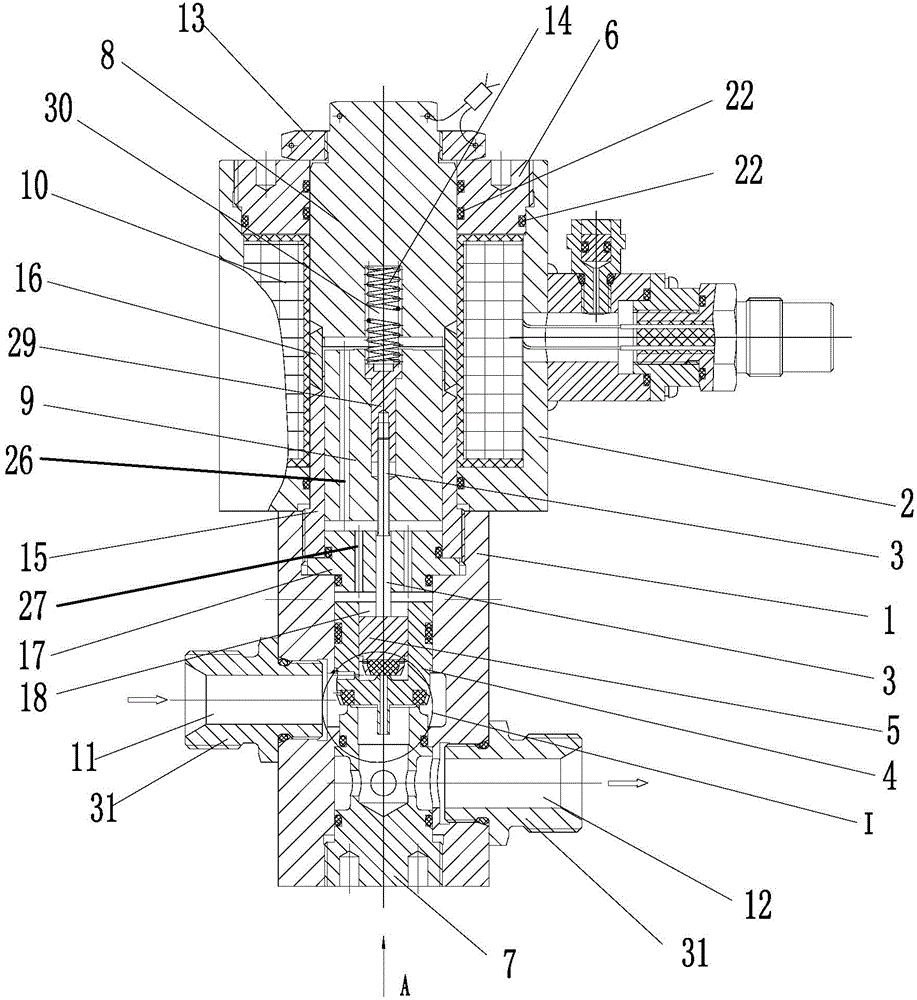
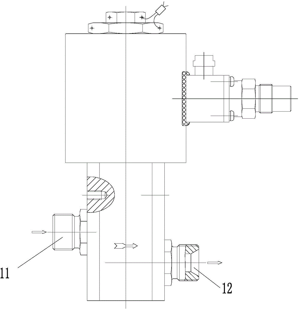
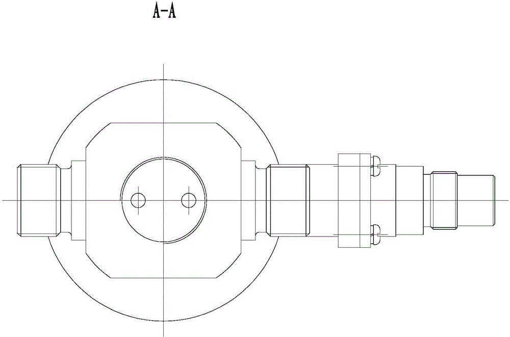
[0047] As shown in the figure, the present invention includes a valve body 1, an electromagnet casing 2, a valve stem 3, a main valve 4, an auxiliary valve 5, a yoke 6, a static iron core 8, a moving iron core 9, and an electromagnetic coil 10; the valve body 1 There are connected flow passages 11 and 12 inside, the electromagnet casing 2 is arranged on the top of the valve body 1, the yoke 6 is arranged on the upper end of the electromagnet casing 2, and the static iron core 8 is connected with the yoke 6; wherein, the main The valve 4 can be made of materials...


PUM


Abstract

The invention discloses a pilot electromagnetic valve. The pilot electromagnetic valve comprises a valve body (1), an electromagnet outer shell (2), a valve rod (3), a main valve (4), an auxiliary valve (5), a yoke (6), a fixed iron core (8), a movable iron core (9) and an electromagnetic coil (10). The main valve (4) is in sliding fit with the interior of the valve body (1) to open or close a flow inlet channel (11) and a flow outlet channel (12), the fixed iron core (8) is connected with the movable iron core (9) through a magnetic core tube, and the magnetic core tube is composed of a first guide sleeve (15) and a second guide sleeve (16); the movable iron core (9) is in sliding fit with the interior of the first guide sleeve (15) and the interior of the second guide sleeve (16); a safety assembly capable of discharging leakage media is arranged on the side wall of the electromagnet outer shell (2) provided with the electromagnetic coil (10); a cavity (18) with which the auxiliary valve (5) is in sliding fit is formed in the main valve (4), and the axial section of the main valve (4) is in a U shape. By means of the pilot electromagnetic valve, the sealing performance is good, the electromagnetic coil can be prevented from being exploded, and the main valve is sensitive in response.

Description

technical field [0001] The invention relates to a valve, in particular to a pilot solenoid valve. Background technique [0002] Pilot-operated solenoid valve means that when the power is turned on, the valve stem is lifted by the electromagnetic force provided by the electromagnetic coil, and the valve port on the pilot hole is opened. At this time, the upper cavity of the solenoid valve is relieved through the pilot hole, forming an up-down and down-high pattern around the main valve core. Pressure difference, under the action of pressure difference, the fluid pressure pushes the main valve core to move upward to open the main valve port; when the power is off, under the action of the spring force and the gravity of the main valve core, the valve stem resets, and the pressure in the upper chamber of the solenoid valve As the pressure rises, the fluid pressure pushes the main valve core to move down, and the main valve port is closed. [0003] The pilot solenoid valve in th...

Claims


Application Information

Patent Timeline
Patent Type & Authority Applications(China)
IPC IPC(8): F16K31/06
CPCF16K31/0675
Inventor 黄小春
Owner NINGBO XINGJIAN SPACE MACHINERY
Learn More