Double rotary wedge variable pitch pneumatic valve actuator

A technology of pneumatic valves and actuators, applied in valve details, valve devices, engine components, etc., can solve the problems of inability to effectively solve the problems of stator and rotor sealing, excessive output torque margin, and increase in the volume of pneumatic devices. The effect of small faults, simple and compact structure, and high positioning accuracy

Active Publication Date: 2017-03-29
HUBEI HIGH & HIGH PRESSURE VALVE CO LTD
View PDF5 Cites 0 Cited by
  • Summary
  • Abstract
  • Description
  • Claims
  • Application Information

AI Technical Summary

Problems solved by technology

[0003] ①The output torque value should not be too large or too small, the valve cannot be opened and closed if it is too small, and the output torque margin that is too large will not only waste energy, but also increase the volume of the pneumatic device, which will not necessarily increase the engineering cost, but also affect the Valves and pipelines cause impacts, which can easily cause pipeline accidents. Therefore, the torque characteristics of an ideal pneumatic device should be basically consistent with the torque characteristics of the valve it is equipped with.
[0006] ④ Due to the low pressure of the air source, it has been proved that the valve pneumatic device is very unlikely to fail due to the strength and rigidity. The quarter-stroke cylinder is different from the straight-stroke cylinder, and it is inevitable to bear a large lateral force. The existing The failure of most valve pneumatic devices is due to the unreasonable guidance of the piston and the repeated unilateral extrusion of the sealing ring, which leads to failure. How to improve the guiding precision of the piston is one of the main issues in the design of pneumatic devices in the future.
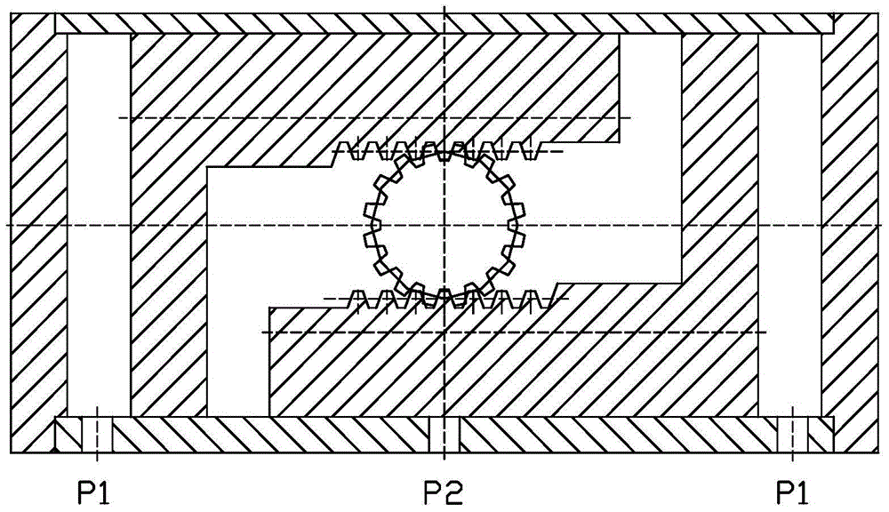
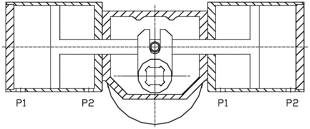
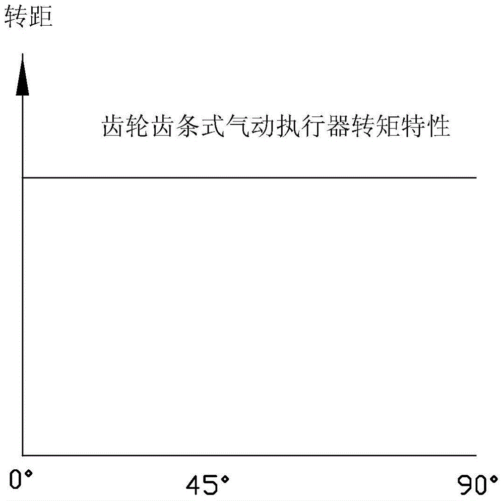
Among them, the swing type rotary cylinder and "air cylinder + mechanical rotary device" are rarely used. The former cannot effectively solve the sealing between the stator and the rotor for a long time, and the latter is currently used in ball valves, butterfly valves and other parts because the mechanism is too large. Pneumatic drive devices for rotary valves are mainly rack-and-pinion and fork-type pneumatic actuators. Their structures are shown in figure 1 , 2 , the output torque characteristic curve see image 3 and Figure 5 , the torque characteristic curves of the ball valve and the butterfly valve respectively refer to Figure 4 and Image 6 , it can be seen from the figure that when the existing rack and pinion and fork pneumatic actuators are used with ball valves and butterfly valves, their torque characteristics are not consistent with those of the valves, which leads to the failure of the rack and pinion and fork pneumatic actuators. The utilization rate of the output power is low, usually less than 50%; when the valve is used for flow regulation, because the output torque and the valve torque are not linear, the excess torque margin will cause a large "forward" to the valve, so The positioning accuracy is low; at the same time, the existing pneumatic actuators still have problems such as large structural size, low utilization rate of internal space, unreasonable guidance of the piston, unstable operation, and great impact on the opening and closing of the valve.

Method used


Image

  • Double rotary wedge variable pitch pneumatic valve actuator
  • Double rotary wedge variable pitch pneumatic valve actuator
  • Double rotary wedge variable pitch pneumatic valve actuator

Examples


Embodiment Construction

[0041] The technical solutions in the present invention will be clearly and completely described below in conjunction with the accompanying drawings in the present invention.

[0042] Please refer to Figure 7-9 One embodiment of the double-rotary wedge variable pitch pneumatic valve actuator of the present invention includes a housing and a main shaft 1 and a piston 11 arranged in the housing. The main shaft 1 is located in the middle of the housing, and the piston 11 is installed on the periphery of the main shaft 1. 11 The axial up and down movement in the housing is realized by the air source pressure.

[0043]Described casing comprises the box body 15 that is positioned at the bottom and the box cover 4 that is positioned at the top, and inner and outer sealing ring (2,7,10,18) is housed on box body 15 and box cover 4, box body 15 and box cover 4 pass screw 21 is fixedly connected, and forms the support at both ends of the main shaft 1 through rolling bearings (3, 17). T...


PUM


Abstract

The invention discloses a dual-rotating-wedge speed-adjusting variable-pitch pneumatic valve actuator which comprises a housing as well as a main shaft and a piston which are arranged in the housing, wherein the main shaft is positioned in the middle of the housing; the piston is mounted at the periphery of the main shaft and can axially move up and down in the housing through air source pressure; two outer rotating wedge grooves passing through a central line are formed in the outer wall of the piston; two inner rotating wedge grooves passing through the central line are formed in the inner wall of the piston; the rotating directions of the outer rotating wedge grooves and the inner rotating wedge grooves are opposite; the outer rotating wedge grooves are matched with an outer pin fixed to the housing and an outer pin sleeve to form primary transmission; the piston rotates clockwise or anticlockwise while moving up and down; the inner rotating wedge grooves are matched with an inner pin fixed to the main shaft and an inner pin sleeve to form secondary transmission; the main shaft rotates clockwise or anticlockwise relative to the piston; the output angle of the main shaft is equal to the sum of two-stage transmission angles. According to the pneumatic valve actuator, the utilization rate of the output power of the pneumatic valve actuator can be greatly increased; the buffering operation can be automatically carried out at the starting and ending stages and the buffering speed is adjustable; the pneumatic valve actuator is simple and compact in structure and long in service life, and has few faults.

Description

technical field [0001] The invention relates to the technical field of pneumatic actuators in industrial automation, in particular to a double-rotary wedge variable-pitch pneumatic valve actuator. Background technique [0002] Under normal circumstances, the 90° angle-stroke pneumatic valve should meet the following conditions when selecting its pneumatic device: [0003] ①The output torque value should not be too large or too small, the valve cannot be opened and closed if it is too small, and the output torque margin that is too large will not only waste energy, but also increase the volume of the pneumatic device, which will not necessarily increase the engineering cost, but also affect the Valves and pipelines cause impacts, which can easily cause pipeline accidents. Therefore, the torque characteristics of an ideal pneumatic device should be basically consistent with the torque characteristics of the valve it is equipped with. [0004] ②In general, the speed of the val...

Claims


Application Information

Patent Timeline
Patent Type & Authority Patents(China)
IPC IPC(8): F16K31/163
CPCF16K31/163
Inventor 喻宏生
Owner HUBEI HIGH & HIGH PRESSURE VALVE CO LTD
Why Eureka
Try Eureka