Control method of regenerative combustion device

A technology of combustion device and control method, which is applied in the direction of combustion method, combination of multiple burners, combustion air/fuel supply, etc., which can solve the problem that exhaust gas temperature affects the safe operation of environmental protection equipment and the recovery rate of total flue gas waste heat is low , Affecting the safe operation of the furnace and other issues, to achieve the effect of improving production and surrounding environment, reducing production labor intensity, and improving reliability and safety

Active Publication Date: 2015-03-25
HUNAN BALING FURNACE ENERGY CONSERVATION
View PDF6 Cites 1 Cited by
  • Summary
  • Abstract
  • Description
  • Claims
  • Application Information

AI Technical Summary

Problems solved by technology

In this kind of regenerative combustion system with paired distributed burners, since the pipe space used to provide combustion-supporting gas for combustion is equal to the flue gas pipe space used for smoke exhaust, the combustion-supporting gas and fuel are mixed and burned to produce The volume of flue gas will increase, and the volume of flue gas under standard conditions is at least 1.1-1.3 times the volume of combustion-supporting gas. High voltage, unsafe state
The existing solution is to add an auxiliary flue to the furnace body to allow about 30% of the high-temperature flue gas to be discharged directly, but this will cause the total waste heat recovery rate of the flue gas to be only 50%-60%, and the exhaust gas temperature is too high Will directly affect the safe operation of environmental protection equipment
[0004] Therefore, poor smoke exhaust, high furnace pressure, and low waste heat recovery rate of the total flue gas are one of the technical problems that have not yet been resolved in the current regenerative combustion technology.
[0005] On the other hand, in the control method of the existing regenerative combustion device, the furnace pressure fluctuates greatly when the direction is changed, and in severe cases, the impact on the furnace is relatively large, which affects the safe operation of the furnace

Method used


Image

  • Control method of regenerative combustion device
  • Control method of regenerative combustion device
  • Control method of regenerative combustion device

Examples


Embodiment Construction

[0056] Embodiments of the present invention will be described in further detail below in conjunction with the accompanying drawings and examples, but those skilled in the art will understand that the following examples are only used to illustrate the present invention, and should not be considered as limiting the scope of the present invention.

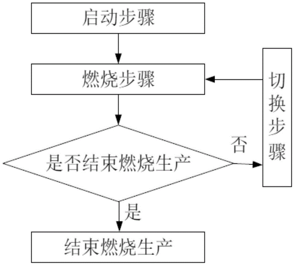
[0057]A control method for a regenerative combustion device provided by the present invention includes a start-up step, a combustion step, a switching step and a circulation step, such as figure 1 shown. A control method of a regenerative combustion device of the present invention and its various steps will be described in detail below in conjunction with the accompanying drawings.

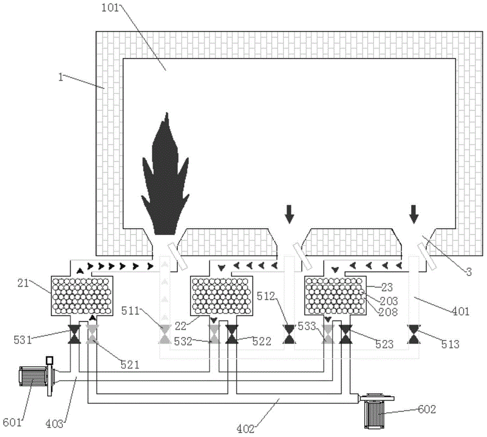
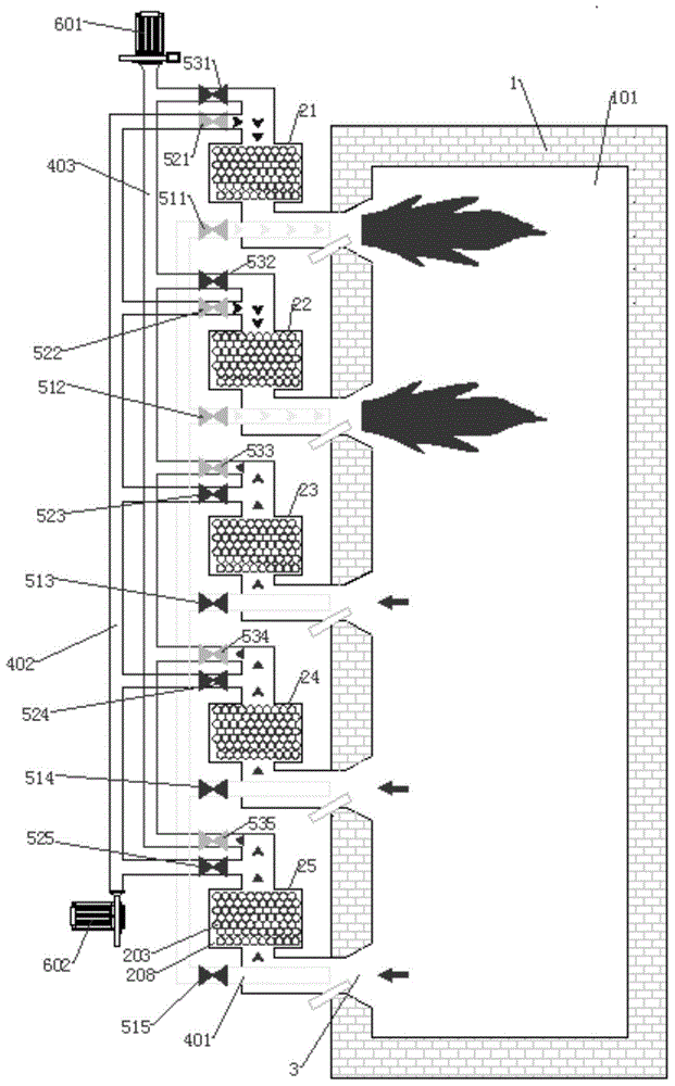
[0058] The starting step includes starting m regenerative burners for combustion, and starting n regenerative burners for smoke exhaust at the same time, where n>m, and n+m≥3, n and m are natural numbers, that is, for smoke exhaust The number of regenera...


PUM


Abstract

The invention provides a control method of a regenerative combustion device. The method includes a starting step, a combustion step, a switching step and a circulation step. Compared with the prior art, the method has the outstanding technical effects of being smooth in smoke exhaust, stable in furnace pressure, small in temperature difference, good in heating quality, remarkable in energy-saving effect and little in pollutant discharge. Thus, the method belongs to an environment coordination type regenerative combustion technology.

Description

technical field [0001] The invention relates to a control method of a combustion device, in particular to a control method of a regenerative combustion device Background technique [0002] Industrial furnaces are the main energy-consuming equipment in industrial production, and the energy consumption accounts for 60% of the total industrial energy consumption. Therefore, the research on its energy-saving technology is of great significance. [0003] Existing industrial furnaces generally use regenerative combustion systems to recover and utilize the waste heat of flue gas. However, the regenerative combustion systems currently used at home and abroad are all arranged in pairs, that is, one group of regenerative burners is used for combustion, and the other group of the same number of regenerative burners is used for smoke exhaust, and the timing is reversed. The heat accumulator alternately stores and releases heat. In this kind of regenerative combustion system with paire...

Claims


Application Information

Patent Timeline
Patent Type & Authority Applications(China)
IPC IPC(8): F23N5/00
CPCF23D23/00F23N5/00F23L2900/15022F27D17/004F27D99/0033F23L15/02F23N2237/02Y02E20/34Y02P80/15
Inventor 周绍芳
Owner HUNAN BALING FURNACE ENERGY CONSERVATION
Why Eureka
Try Eureka