Heat pump system having waste heat recovery structure with 2nd evaporation

A heat pump system and technology for recovering waste heat, applied to compressors with multiple evaporators, heat pumps, superheaters, etc., can solve the problems of lower efficiency, increased cost structure, compressor stop working, etc., to reduce production costs, Save operating energy and prevent overload

Active Publication Date: 2015-03-25
BOOSUNG ENG
View PDF7 Cites 6 Cited by
  • Summary
  • Abstract
  • Description
  • Claims
  • Application Information

AI Technical Summary

Problems solved by technology

[0005] Similarly, in the case of compressors in the prior art, except for high-pressure compressors, there are restrictions on the temperature and pressure of the refrigerant input into the compressor. In the configuration of the heat pump, there should be a high-pressure refrigerant and a heat pump system. Since the cost and maintenance management costs required to configure such a system are high, it is urgent to develop a new heat pump system.
[0006] Therefore, there are many problems in providing high temperature in the cooling and heating system in the prior art, that is, in order to increase the temperature to a high temperature, it is necessary to have a high-temperature and high-pressure compressor, or to make the general compressor work for a long time, which not only reduces the efficiency, It may cause compressor overload, stop the compressor, or freeze in the piping between the compressor and the first-stage evaporator. In order to provide high-temperature heat, it is necessary to install an additional heater, etc. There are many problems in terms of increased cost and structure

Method used


Image

  • Heat pump system having waste heat recovery structure with 2nd evaporation
  • Heat pump system having waste heat recovery structure with 2nd evaporation
  • Heat pump system having waste heat recovery structure with 2nd evaporation

Examples


Embodiment Construction

[0016] The features of the present invention can be more clearly understood by referring to the accompanying drawings for the following detailed description of a heat pump system having a structure for recovering waste heat through a two-stage evaporator according to the present invention.

[0017] On the other hand, in the description of the embodiments, detailed descriptions of constituent elements that are widely known and used in the field or those that do not belong to the field are omitted here. The purpose of omitting unnecessary descriptions is for clarity. convey the gist of the invention.

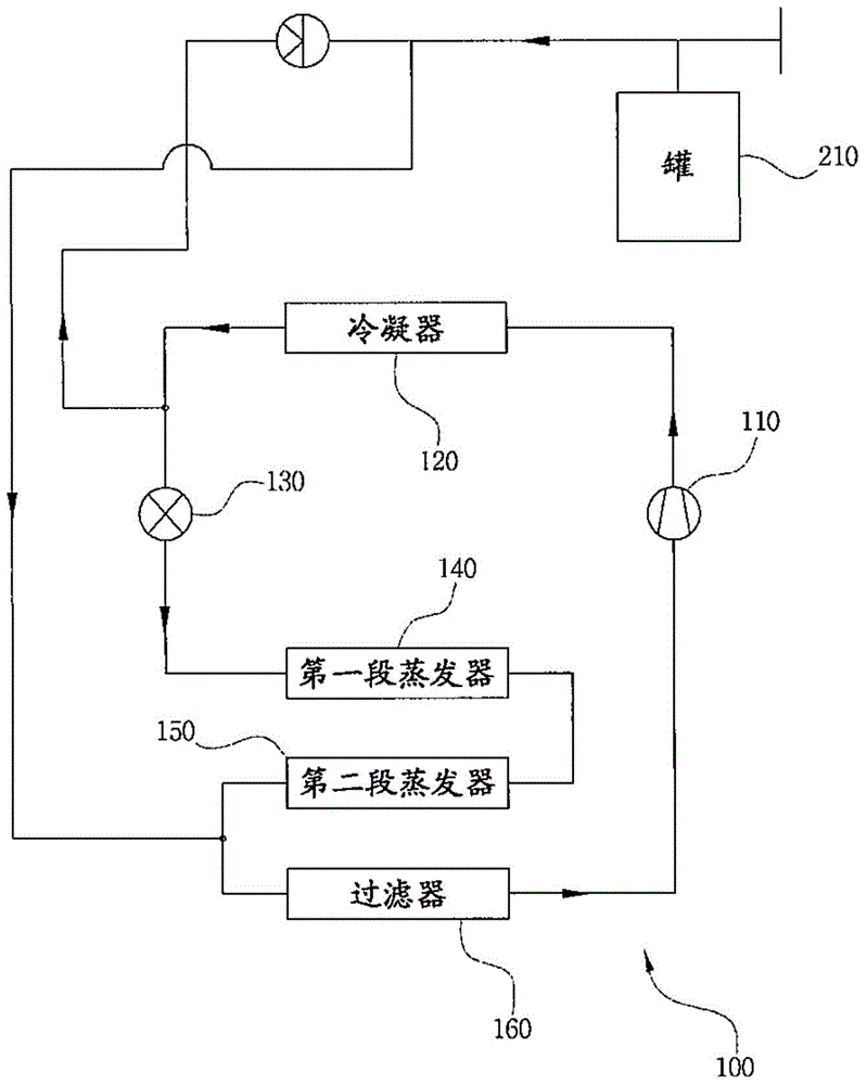
[0018] figure 1 It is a schematic diagram illustrating a heat pump system with a structure for recovering waste heat through two-stage evaporators according to an embodiment of the present invention.

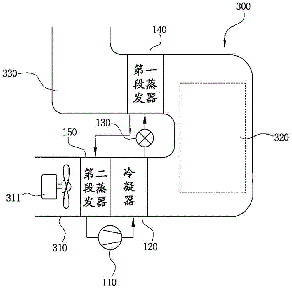
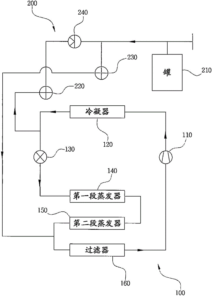
[0019] Thus, the heat pump system with the structure of recovering waste heat through two-stage evaporators is briefly described, and the heat pump (100) includes a compressor (110...


PUM


Abstract

The present invention relates to a heat pump system having a waste heat recovery structure with 2nd evaporation and, more specifically, to a heat pump system having a waste heat recovery using a secondary evaporator capable of recovering waste heat discharged from a heat pump cycle to the outside using a primary evaporator, and passing a refrigerant, overheated by the recovered heat, through a secondary evaporator to radiate heat, thus providing a function for supplying initially induced air to a condenser in a pre-heated status and saving operational energy and preventing an overload of a compressor, in proportion to the heat energy reused in the condenser. The heat pump system comprises a compressor (110), a condenser (120), an expansion valve (130), a primary evaporator (140) and a secondary evaporator (150). The condenser (120) provides a function for supplying heated air, and the secondary evaporator (150) is positioned at the front end of the condenser (120) to preheat the initially induced air.

Description

technical field [0001] The present invention relates to a heat pump system having a structure for recovering waste heat through two-stage evaporators, and more specifically, relates to recovering waste heat discharged to the outside in a heat pump cycle by using a first-stage evaporator, and then turning it into a superheated steam state by the recovered heat The refrigerant passes through the second-stage evaporator and releases heat, thereby preheating the initially input air and providing air in a preheated state to the condenser. By providing this function, it can be proportional to the heat energy recycled in the condenser Alleviate the overload of the compressor and save the operating energy of the compressor. Background technique [0002] Generally speaking, a heat pump is a cooling and heating device that uses the heating or condensation heat of a refrigerant to conduct a low-temperature heat source to a high temperature or to conduct a high-temperature heat source t...

Claims


Application Information

Patent Timeline
Patent Type & Authority Applications(China)
IPC IPC(8): F25B5/04
CPCF25B5/04F25B27/00F25B30/02F25B40/06F25B43/003Y02P80/15
Inventor 金庆天
Owner BOOSUNG ENG
Why Eureka
Try Eureka