
Turbocharger rotor unbalance amount control method based on dynamic characteristics

A turbocharger and rotor unbalanced technology, applied in static/dynamic balance testing, instruments, measuring devices, etc., can solve problems such as increased production and maintenance costs, unbalanced vibration control, and large vibration of turbochargers. Achieve the effects of reducing unbalanced vibration faults, prolonging service life, and saving maintenance costs

Active Publication Date: 2015-03-25
宁波丰沃增压科技股份有限公司
View PDF6 Cites 18 Cited by
  • Summary
  • Abstract
  • Description
  • Claims
  • Application Information

AI Technical Summary

Problems solved by technology

However, the rotor unbalance control method has always had few solutions, especially for the special high-speed microstructure of the turbocharger.
After the design of the turbocharger, the manufacturer or factory performs high-speed dynamic balancing to balance the rotor system, or the dynamic balancing measures are carried out after the design is completed. It has not been considered in the turbocharger design and manufacturing process, resulting in the need for unbalanced vibration control during the actual working process of the turbocharger, resulting in excessive vibration of the turbocharger, reduced performance, and even increased unnecessary production maintenance cost

Method used


Image

  • Turbocharger rotor unbalance amount control method based on dynamic characteristics
  • Turbocharger rotor unbalance amount control method based on dynamic characteristics
  • Turbocharger rotor unbalance amount control method based on dynamic characteristics

Examples


Embodiment Construction

[0029] The present invention will be further described below in conjunction with the accompanying drawings.

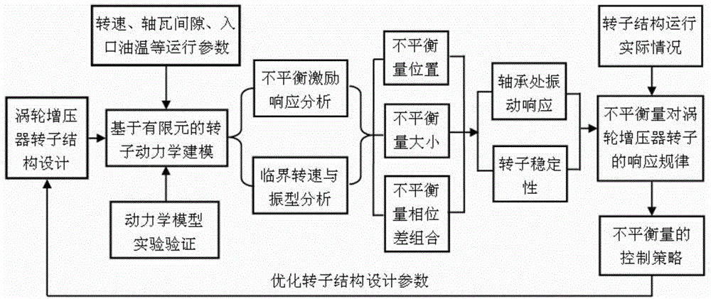
[0030] like figure 1 Shown, the present invention comprises the steps:

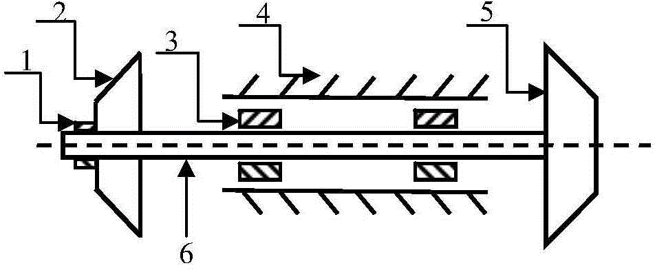
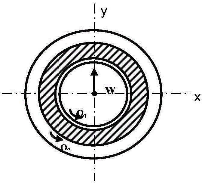
[0031] 1) When designing a turbocharger, analyze the structural characteristics of the rotor bearing of the turbocharger, and establish the motion control equation of the rotor system Where M is the mass matrix, C is the external damping matrix of the system, G is the gyro force matrix, K is the system stiffness matrix, q, with represent displacement, velocity and acceleration respectively, F i is the internal oil film force of the supporting journal, F ub is the unbalanced force, F s is the static load gravity. According to the structural size parameters of the floating ring bearing, combined with the bearing bush installation clearance, lubricating oil temperature, lubricating oil viscosity, floating ring bearing speed and the actual operating parameters of the static load at the two bea...


PUM


Abstract

The invention discloses a turbocharger rotor unbalance amount control method based on dynamic characteristics. The method comprises the steps that a turbocharger rotor bearing system dynamics finite element solid model is built; (2) different unbalance amount excitation modes are applied to the dynamics finite element solid model, and vibration responses and stability rules of turbocharger rotor unbalance position, size and phase difference to the measuring points of two bearings are summarized; (3) the optimum allocation scheme of unbalance excitation on the rotor position, size and phase difference is determined with the minimum root-mean-square value of the vibration amplitude as the judging criteria; (4) turbocharger rotor structure parameters are optimized until the vibration amplitudes at the positions of the two turbocharger rotor bearings are the minimum and the stability at the positions of the two turbocharger rotor bearings is the best. According to the turbocharger rotor unbalance amount control method, unbalance control is applied in the turbine end and air pressing end structure design and manufacturing process, stable and efficient running of the whole machine can be achieved, and unbalance vibration faults caused in the rotor running process are effectively reduced.

Description

technical field [0001] The invention belongs to the field of turbocharger dynamics and vibration control, in particular to a method for controlling the unbalanced amount of a turbocharger rotor based on dynamic characteristics. Background technique [0002] Turbocharging technology is an important way for vehicles to save energy and reduce consumption. At present, exhaust gas turbocharging technology has been widely used in engines. Supercharging has become an effective measure to improve engine power, economic benefits and emission standards. Facing new changes in energy supply and demand patterns and new trends in international energy development, based on my country's basic National conditions, focusing on the scientific development concept, keeping up with the new trend of international energy technology, coupled with the low production cost of turbochargers for small vehicles and the effective use of exhaust gas to drive turbines to make energy recycling a key technology...

Claims


Application Information

Patent Timeline
IPC IPC(8): G01M1/38
Inventor 宾光富王龙凯李学军蒋玲莉何宽芳高永毅沈意平
Owner 宁波丰沃增压科技股份有限公司
Learn More