
Novel broadband high-average-power air cooling structure output window

An average power, air-cooled structure technology, applied to the cooling method of the transit time type electron tube, the transit time type electron tube, the coupling device of the transit time type electron tube, etc., can solve the problem of poor thermal conductivity and reduce the power capacity of the output window , Narrow working bandwidth and other issues, to achieve the effect of expanding the working bandwidth, increasing the working stability and improving the power capacity

Inactive Publication Date: 2015-03-25
UNIV OF ELECTRONIC SCI & TECH OF CHINA
View PDF16 Cites 6 Cited by
  • Summary
  • Abstract
  • Description
  • Claims
  • Application Information

AI Technical Summary

Problems solved by technology

The traditional single-window structure output window is also used in some gyro-traveling-wave tubes, but its working bandwidth is narrow, which greatly limits the working bandwidth of the gyro-traveling-wave tube
In order to expand the working bandwidth of the output window, there is also an output window with a double-window structure, but the relative working bandwidth of the output window of this type of structure is only about 10%. Said that the double window structure output window can no longer meet the demand
In addition, the output windows of the two traditional structures mentioned above both use the edge cooling method of the window to cool the output window. Due to the poor thermal conductivity of the general output windows, such as sapphire windows and alumina ceramic windows, when When this type of output window transmits electromagnetic waves with high average power, the center of the window cannot be effectively cooled, resulting in a large temperature difference from the center to the edge of the output window, thereby reducing the power capacity of the output window

Method used


Image

  • Novel broadband high-average-power air cooling structure output window
  • Novel broadband high-average-power air cooling structure output window
  • Novel broadband high-average-power air cooling structure output window

Examples


Embodiment Construction

[0026] Taking the output window of broadband high average power air-cooled structure with a working center frequency of 34 GHz and a working mode of TE01 mode as an example, the present invention will be further described in detail below.

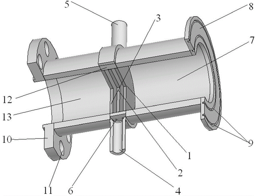
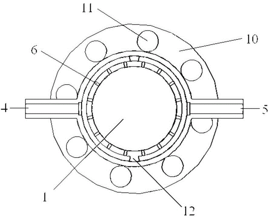
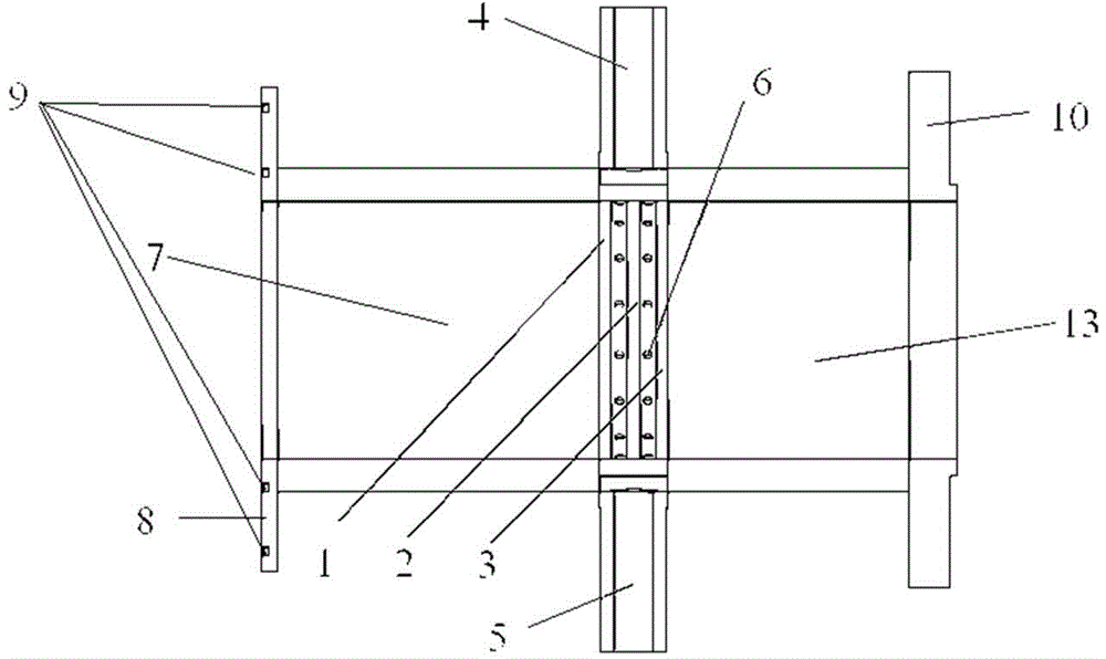
[0027] attached figure 1 is the 3D cross-sectional view of the output window, figure 2 is the transverse section of the output window; image 3 It is the longitudinal section of the output window; the output window includes: three sapphire output windows (including the first window (1), the second window (2), and the third window (3)); There are two silver-copper solder grooves (9) for welding on the input connecting flange (8); one is connected with the gyroscopic traveling wave tube antenna feed system or large The output connection flange (10) connected to the power water load has eight screw holes (11) for connection on the output connection flange (10); one section of input waveguide (7) and one section of output waveguide (13), its...


PUM


Abstract

The invention discloses a novel broadband high-average-power air cooling structure output window and relates to an output window of a microwave and millimeter-wave electric vacuum device, in particular to a broadband high-average-power output window of a gyro traveling wave tube. According to the output window, one layer of window plate or double layers of window plates adopted in the prior art are replaced with three layers of window plates, the three layers of window plates are arranged on a window plate installation ring at intervals, ventilation holes connected with cavities between the adjacent window plates are formed in the window plate installation ring, the window plates are cooled through the ventilation holes, and then the operation bandwidth of the output window is effectively expanded and the power capacity of the output window is effectively improved.

Description

Technical field [0001] The invention relates to an output window structure of a microwave and millimeter wave electric vacuum device, in particular to a broadband high average power output window structure of a cyclotron traveling wave tube. Background technique [0002] The output window is one of the key components of microwave and millimeter wave electric vacuum devices. Its main function is to separate the vacuum environment in microwave and millimeter wave electric vacuum devices from the atmosphere to ensure the high vacuum degree in electric vacuum devices; High-power microwaves and millimeter waves generated by wave electric vacuum devices. [0003] The design of the output window is directly related to the output performance of the electric vacuum device and even the success or failure of the development of the whole tube. The difficulty of output window design mainly includes two aspects, one is the problem of output bandwidth, and the other is the problem of powe...

Claims


Application Information

Patent Timeline
IPC IPC(8): H01J23/36H01J23/00
CPCH01J23/36H01J23/005
Inventor 徐勇罗勇杨利亚王建勋蒲友雷鄢然王丽
Owner UNIV OF ELECTRONIC SCI & TECH OF CHINA
Learn More