
WiFi antenna applied to metal frame mobile phone

A metal frame, mobile phone technology, applied in antenna equipment with additional functions, radiating element structure and other directions, to achieve excellent antenna performance, easy manufacturing and integration, and overcome the effects of large back lobes

Active Publication Date: 2015-03-25
NANJING HOWKING COMM TECH
View PDF6 Cites 6 Cited by
  • Summary
  • Abstract
  • Description
  • Claims
  • Application Information

AI Technical Summary

Problems solved by technology

Especially for the mobile phones with metal frame that are popular in the market now, how to overcome the adverse effect of the metal frame on the performance of the built-in antenna of the mobile phone and maintain excellent antenna performance has become a major problem in the design of mobile phone antennas

Method used


Image

  • WiFi antenna applied to metal frame mobile phone
  • WiFi antenna applied to metal frame mobile phone
  • WiFi antenna applied to metal frame mobile phone

Examples


Embodiment 1

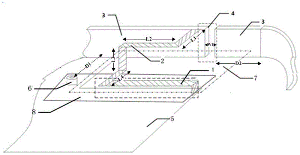
[0022] Example 1: Such as figure 1 The shown WiFi antenna for mobile phone with metal frame is placed in the upper left corner of the front of the mobile phone and connected with the metal frame 3 of the mobile phone, including a section of 50Ω microstrip feeder 1. The 50Ω microstrip feeder 1 is 13mm long and wide is 1mm, and is connected to the metal frame 3 through a space-folded metal strip 2. The metal strip 2 is divided into four sections, and the dimensions of the four sections are L1=2.06mm, L2=13mm, L3=1.1mm, L4= 1.8mm, the width of the metal strip 2 is 1mm, and the metal frame 3 is electrically connected to the metal partition 5 in the middle layer of the mobile phone. The metal partition 5 has a rectangular window 7 (the length of which is 15mm parallel to the side of the frame with the narrow slit 4) to form a clear area, and the metal strip 2 and the 50Ω microstrip feeder 1 are located in the clear area; the upper left end of the metal frame 3 A section is cut o...


PUM

PropertyMeasurementUnit
Lengthaaaaaaaaaa
Lengthaaaaaaaaaa
Lengthaaaaaaaaaa

Abstract

The invention discloses a WiFi antenna applied to a metal frame mobile phone. The WiFi antenna applied to the metal frame mobile phone comprises a metal frame of the mobile phone, a 50 omega microstrip feeder, a metal strip band and a metal separating plate located in the middle layer of a body of the mobile phone, wherein a narrow seam is formed in the metal frame, one end of the metal strip band is connected with the 50 omega microstrip feeder, the other end of the metal strip band is connected with the metal frame at the position near the narrow seam of the metal frame, and the metal frame is electrically connected with the metal separating plate. The WiFi antenna applied to the metal frame mobile phone reasonably uses the metal frame of the mobile phone, takes the metal frame as part of an antenna radiation unit, controls the distribution of radiation current on the metal frame by additionally arranging the narrow seam in the metal frame, controls the current route of the antenna by the arrangement of the metal strip band, the metal frame and a grounded point, and changes the distribution of a radiation electricity field, thereby meeting the requirements for the work frequency band and bandwidth of the mobile phone antenna.

Description

technical field [0001] The invention relates to a mobile communication terminal antenna, in particular to a WiFi antenna for a metal frame mobile phone. Background technique [0002] Due to their fashion, portability, and increasingly comprehensive functions, mobile phones have become the largest category of personal electronic consumer products in the world. The antenna used to send and receive radio waves is undoubtedly one of the most important components in wireless communication. The performance of the antenna directly affects the performance of the wireless communication system. With the maturity of 3G / 4G technology and the popularization of smart phones, mobile phones have developed from only basic call functions to Bluetooth, GPS, mobile TV, WiFi and other functions. In order to meet the needs of multiple functions, correspondingly, in addition to a main antenna, the mobile phone also needs to be equipped with multiple antennas with functions such as Bluetooth, WiFi...

Claims


Application Information

Patent Timeline
IPC IPC(8): H01Q1/44H01Q1/36
Inventor 陈平蒯振起朱晓维张彦罗清唐小芳陆从乐
Owner NANJING HOWKING COMM TECH
Learn More