
Aerodynamic device and aerodynamic automobile applying aerodynamic devices

An aerodynamic and cylinder technology, which is applied in the direction of power plant, vehicle parts, transportation and packaging, etc., can solve the problems of low mileage, weak work continuity, inability to realize aerodynamic system, etc., and achieves convenient acquisition and low cost Effect

Pending Publication Date: 2018-11-06
罗邦琴
View PDF2 Cites 0 Cited by
  • Summary
  • Abstract
  • Description
  • Claims
  • Application Information

AI Technical Summary

Problems solved by technology

[0006] Although the above-mentioned structure uses air as the driving energy of the car, the inflation of the air needs to work through the rocker arm or the threaded rod air compressor, so it is impossible to realize a circulating aerodynamic system that is completely separated from electricity. After driving for a certain distance, it is necessary to use external force or electricity to inflate, resulting in the actual mileage of this kind of aerodynamic vehicle is not high, and the work continuity is not strong

Method used


Image

  • Aerodynamic device and aerodynamic automobile applying aerodynamic devices
  • Aerodynamic device and aerodynamic automobile applying aerodynamic devices
  • Aerodynamic device and aerodynamic automobile applying aerodynamic devices

Examples


Embodiment Construction

[0027] The following will clearly and completely describe the technical solutions in the embodiments of the present invention with reference to the accompanying drawings in the embodiments of the present invention. Obviously, the described embodiments are only some, not all, embodiments of the present invention.

[0028] In describing the present invention, it should be understood that the terms "upper", "lower", "front", "rear", "left", "right", "top", "bottom", "inner", " The orientation or positional relationship indicated by "outside", etc. is based on the orientation or positional relationship shown in the drawings, and is only for the convenience of describing the present invention and simplifying the description, rather than indicating or implying that the referred device or element must have a specific orientation, so as to Specific orientation configurations and operations, therefore, are not to be construed as limitations on the invention.

[0029] refer to Figure ...


PUM


Abstract

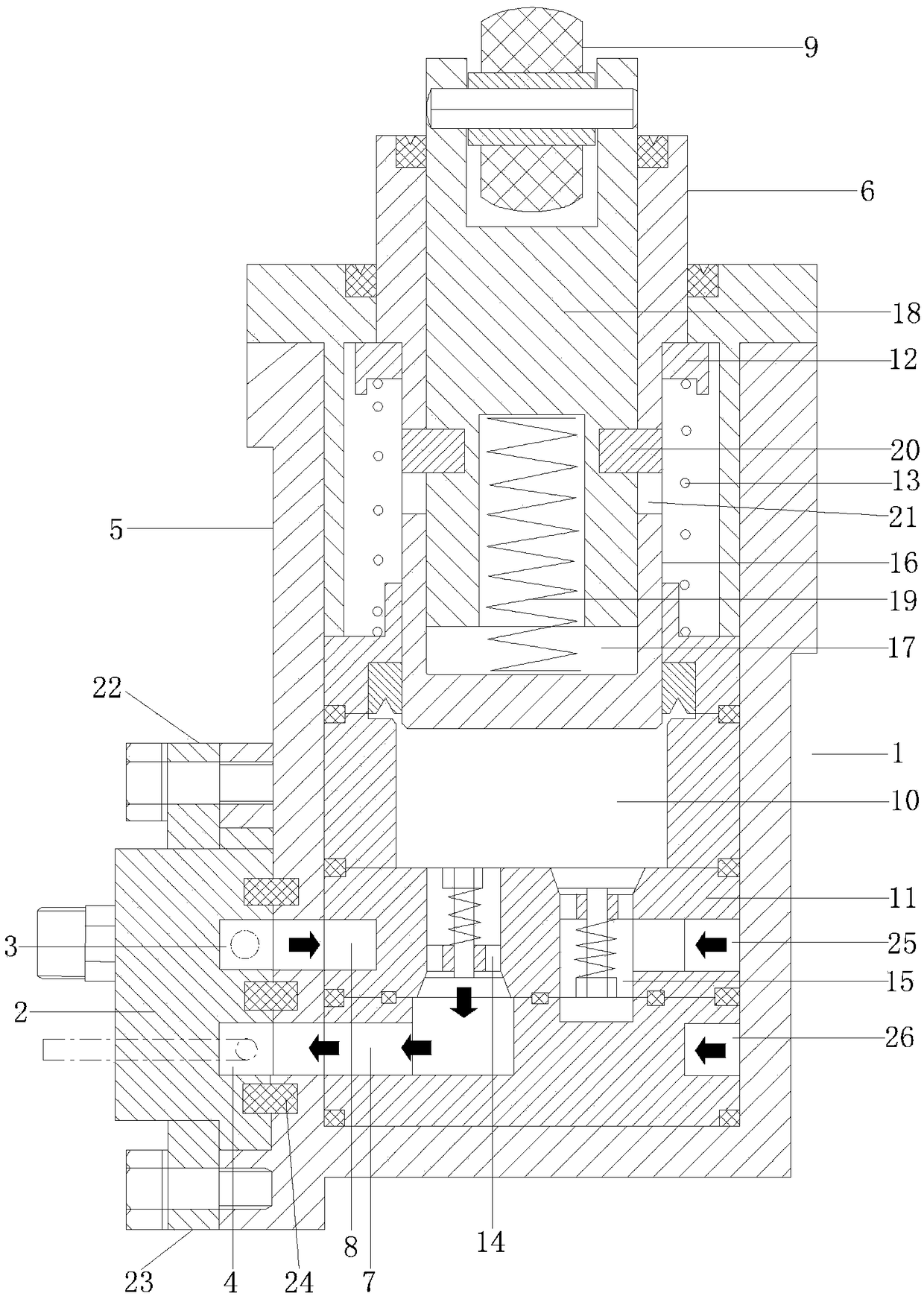
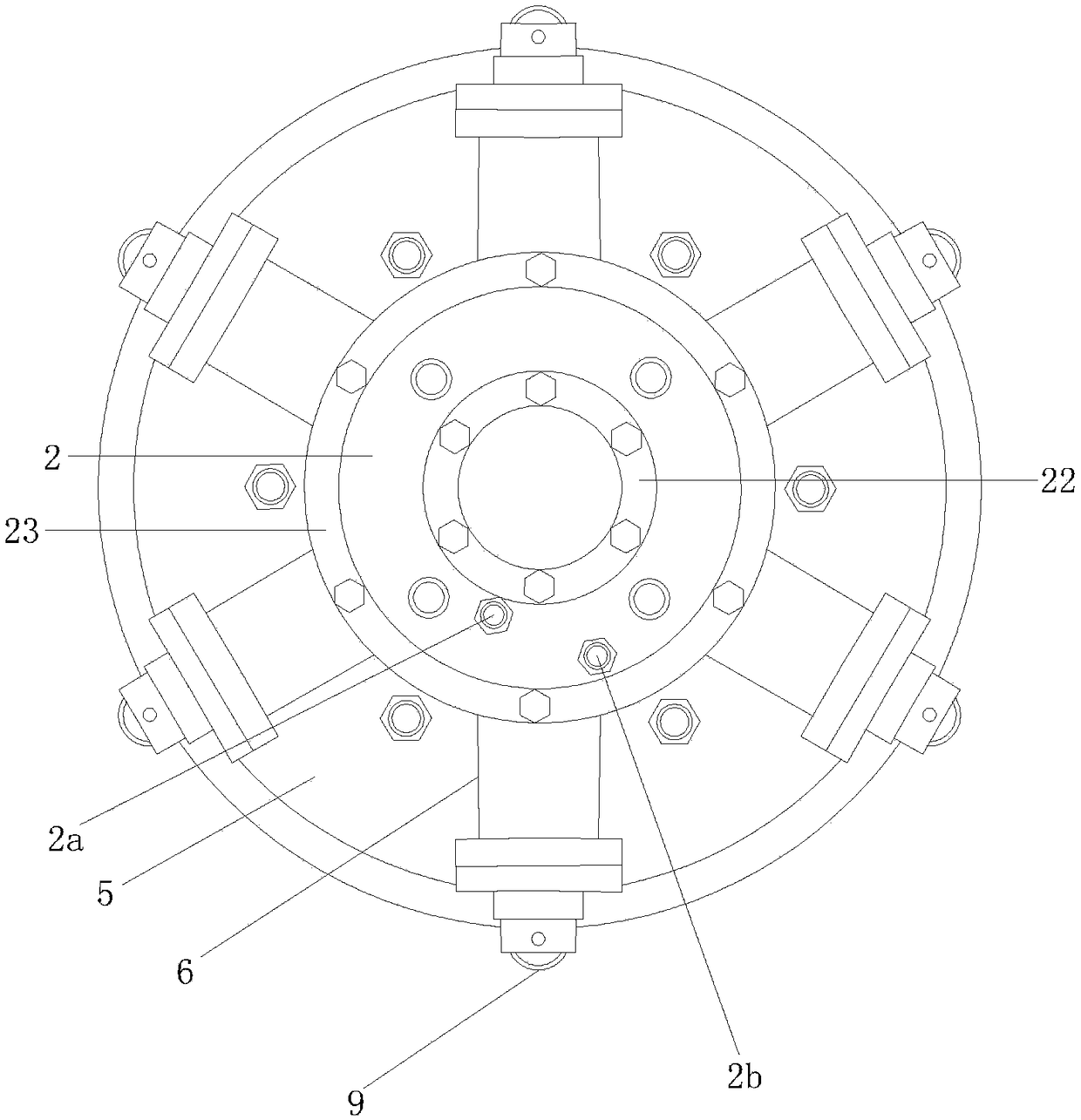
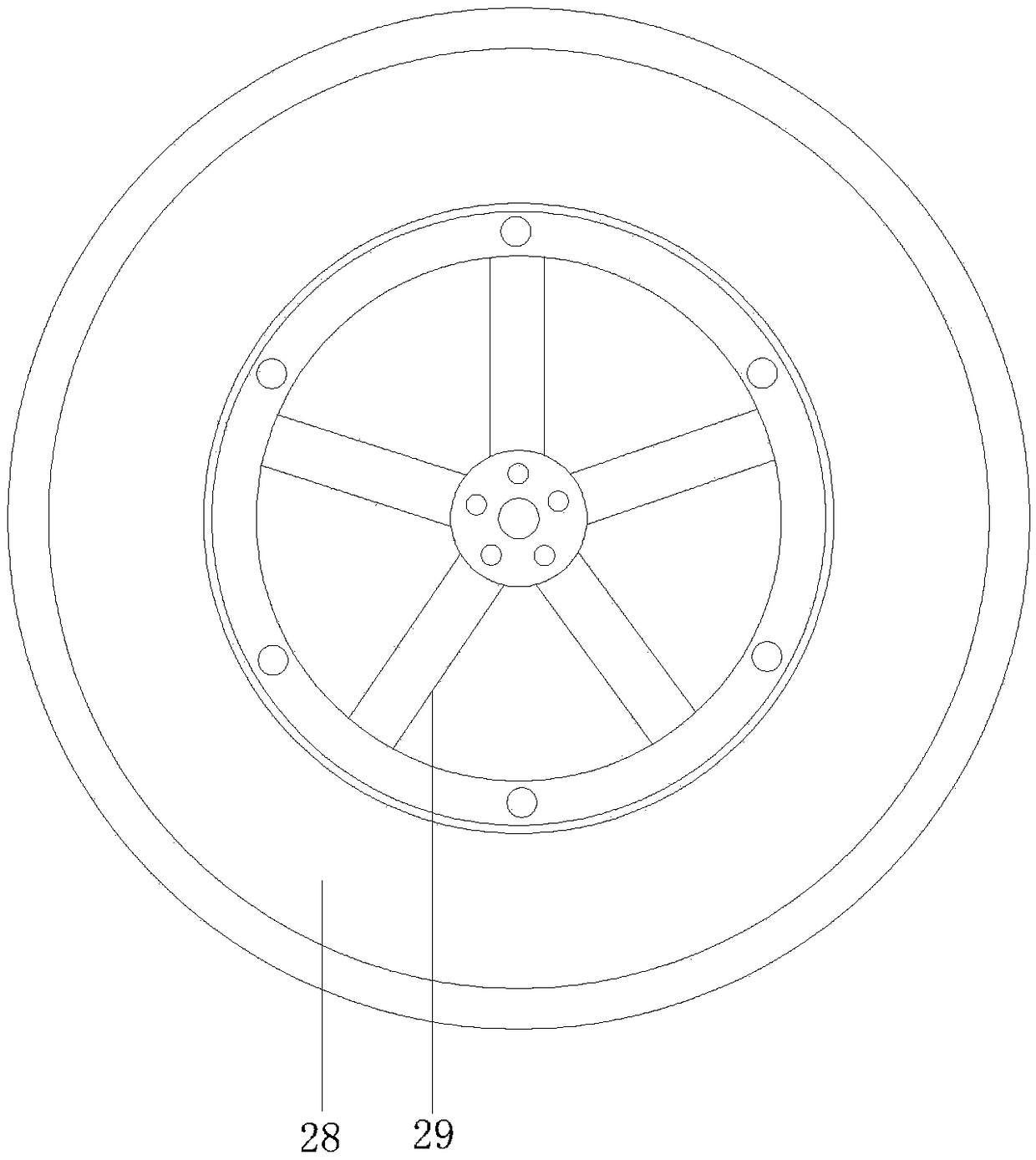
The invention discloses an aerodynamic device and an aerodynamic automobile applying the aerodynamic devices. The defects that work continuity is low and a complete pollution-free effect cannot be achieved in the prior art are overcome. The aerodynamic automobile comprises an automobile body provided with an air storage tank, an air motor and the aerodynamic devices. Each aerodynamic device comprises an air disc located in the center position of a tire. Aerodynamic pumps are fixed to hubs of the automobile body. The air discs are connected with the aerodynamic pumps. The aerodynamic pumps, theair discs and the air storage tank are connected and communicate. The outer ends of plungers of multiple air cylinders of the aerodynamic pumps extend out of the tires. The air motor drives the tiresto rotate. Under the gravity of the automobile and the ground counteracting force, the plungers are pressed to act, and the automobile travels and is inflated with air serving as a power source at the same time. The aerodynamic automobile has the beneficial effects of being free of emission and pollution, long in working time, capable of obtaining energy conveniently and wide in market prospect.

Description

technical field [0001] The invention relates to the technical field of machinery, in particular to an aerodynamic device and an aerodynamic vehicle using the aerodynamic device. Background technique [0002] With the gradual promotion of new energy vehicles, this zero-emission, non-polluting vehicle working method has gradually become popular among the people. However, today's new energy vehicles are often driven by electricity, and the production of thermal power in the production of electricity still has a negative impact on the environment. Therefore, it cannot be truly completely pollution-free; at the same time, electric new energy vehicles need to build charging piles, which greatly increases the cost of using the vehicle. Therefore, new energy electric vehicles have relatively large defects, while existing The technology of aerodynamic vehicles is not mature, for example: [0003] The aerodynamic vehicle disclosed in Chinese patent literature, application publication...

Claims


Application Information

Patent Timeline
Patent Type & Authority Applications(China)
IPC IPC(8): B60K8/00
CPCB60K8/00
Inventor 罗邦琴
Owner 罗邦琴
Learn More