
12 kV solid insulation single-phase and single-cavity sealed type shell

A solid insulation and shell technology, which is used in the installation of substation/distribution device shells, switchgear with resin shells, etc. Poor ability, etc.

Inactive Publication Date: 2015-03-25
ZHUHAI KELI ELECTRIC
View PDF5 Cites 0 Cited by
  • Summary
  • Abstract
  • Description
  • Claims
  • Application Information

AI Technical Summary

Problems solved by technology

[0003] The purpose of the present invention is to provide a 12kV solid insulation single-phase single-cavity solid-sealed housing, which effectively solves the problem that the traditional switchgear insulation housing cannot realize the miniaturization of the structure under the condition of 12kV voltage level, and the metal housing is easily polluted. Corrosion, environmental pollution of conductive components and insulating parts in the cabinet Poor condensation ability, low level of internal fault arc, various and complex components and accessories, and the structural design of solid insulating materials are easy to form water droplets and dust collectors due to condensation to cause insulation Partial discharge indicators of devices do not meet the requirements of the power transmission and distribution industry due to failure and improper surface technology treatment, the overall structure is too large and the assembled products occupy a large area, and the structure design of different cavity structures cannot be used universally, resulting in different usage methods or Difficulties in installation at the construction site due to inconsistencies in the overall layout and size of the product in the combined state, difficulty in stability due to installation and debugging of mechanical characteristic parameters after assembly, acceptance of the five-proof requirements for the overall cabinet, and a series of installation layout problems such as power failure and power transmission procedures

Method used


Image

  • 12 kV solid insulation single-phase and single-cavity sealed type shell
  • 12 kV solid insulation single-phase and single-cavity sealed type shell
  • 12 kV solid insulation single-phase and single-cavity sealed type shell

Examples


Embodiment Construction

[0024] The present invention and specific implementation thereof are described in further detail below in conjunction with accompanying drawing:

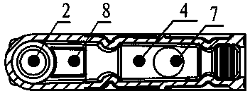
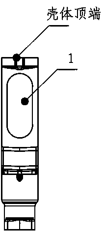
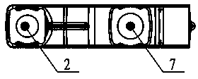
[0025] see Figure 1 to Figure 5 , the present invention comprises a shell made of solid epoxy resin, a cavity 5 is provided in the shell, an opening communicating with the cavity 5 is provided on the top of the shell 5, and an oval opening 1 is provided on the front outer wall of the shell 5 , the rear lower part of the housing 5 is provided with a cylindrical cavity 2, which is characterized in that: between the cylindrical cavity 2 and the housing is a silica gel layer 3, the bottom of the cavity 5 is inlaid with a conductor 8, and the conductor 8 and the cylinder The body cavities 2 are isolated by the silica gel layer 3 , and the bottom of the cavity 5 is provided with a hole 7 , and the conductor 8 is between the cylinder cavity 2 and the hole 7 .

[0026] The center of the plane of the elliptical opening 1 is located on the ...


PUM


Abstract

The invention discloses a 12 kV solid insulation single-phase and single-cavity sealed type shell. The 12 kV solid insulation single-phase and single-cavity sealed type shell comprises a shell body made of solid epoxy resin, wherein a cavity 5 is formed in the shell body, an opening communicated with the cavity 5 is formed in the top of the shell body, an elliptic hole 1 is formed in the upper portion of the outer wall of the front face of the shell body, and a cylinder cavity 2 is formed in the lower portion of the rear face of the shell body. The 12 kV solid insulation single-phase and single-cavity sealed type shell is characterized in that a silica gel layer 3 is arranged between the cylinder cavity 2 and the shell body, an electric conductor 8 is embedded in the bottom of the cavity 5, the electric conductor 8 and the cylinder cavity 2 are isolated through the silica gel layer 3, a hole 7 is formed in the bottom of the cavity 5, and the electric conductor 8 is arranged between the cylinder cavity 2 and the hole 7.

Description

technical field [0001] The invention relates to an insulating shell of a switch cabinet, in particular to a 12kV solid insulating single-phase single-cavity solid-sealed shell. Background technique [0002] In the existing power transmission and distribution system, the housings of the air-insulated switchgear with a voltage level of 12kV and below all adopt a three-phase common type, metal plate isolation and sealing, and an overall large-space cavity structure with no interval between the three phases (three phases share one cavity) body). The original large cavity technology cannot realize the miniaturization of the structure under the condition of this voltage level, the metal shell is easy to be polluted and corroded, the environmental pollution condensation ability of the conductive components and insulating parts in the cabinet is poor, the internal fault arc level is low, and the components The accessories are varied and complex. However, in some large-cavity shell...

Claims


Application Information

Patent Timeline
IPC IPC(8): H02B1/26
CPCH02B13/01H02B1/26
Inventor 廉世军杨敢甘钦荣张路明
Owner ZHUHAI KELI ELECTRIC
Learn More