A tool for heat treatment and shaping of large blades

A large blade and tool technology, applied in the field of large blade heat treatment and shaping tools, can solve the problems that the blade cannot meet, there is internal stress, blade rebound, etc., to achieve stable and lasting clamping effect, improve processing quality, and ensure the effect of assembly requirements.

Active Publication Date: 2019-04-16
HARBIN TURBINE +1
View PDF6 Cites 0 Cited by
  • Summary
  • Abstract
  • Description
  • Claims
  • Application Information

AI Technical Summary

Problems solved by technology

[0003] The purpose of the present invention is to solve the problem that the large blades of the steam turbine will be deformed and have internal stress when the gas channel profile is processed and the Stellite alloy sheet is welded. , the internal stress inside the blade leads to the spring back when the blade is assembled, so that the assembly of the blade cannot meet the assembly requirements of the blade crown, and then provides a heat treatment shaping tool for large blades

Method used


Image

  • A tool for heat treatment and shaping of large blades
  • A tool for heat treatment and shaping of large blades
  • A tool for heat treatment and shaping of large blades

Examples


specific Embodiment approach 1

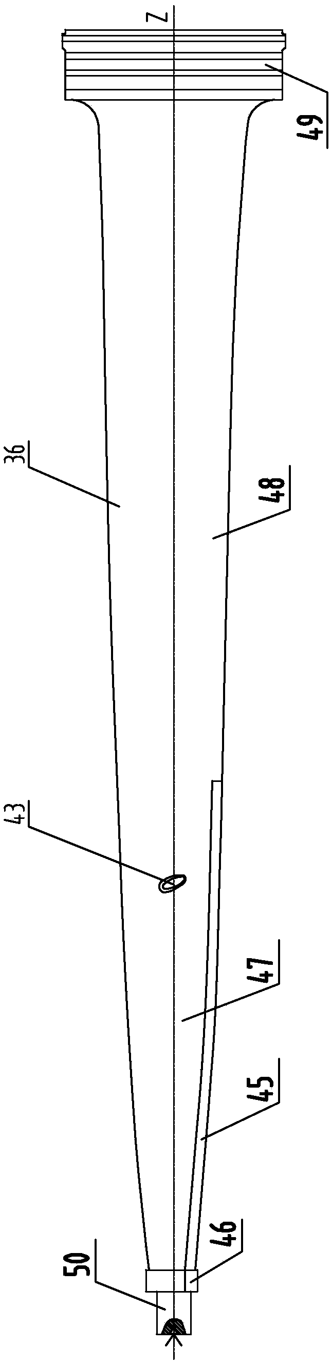
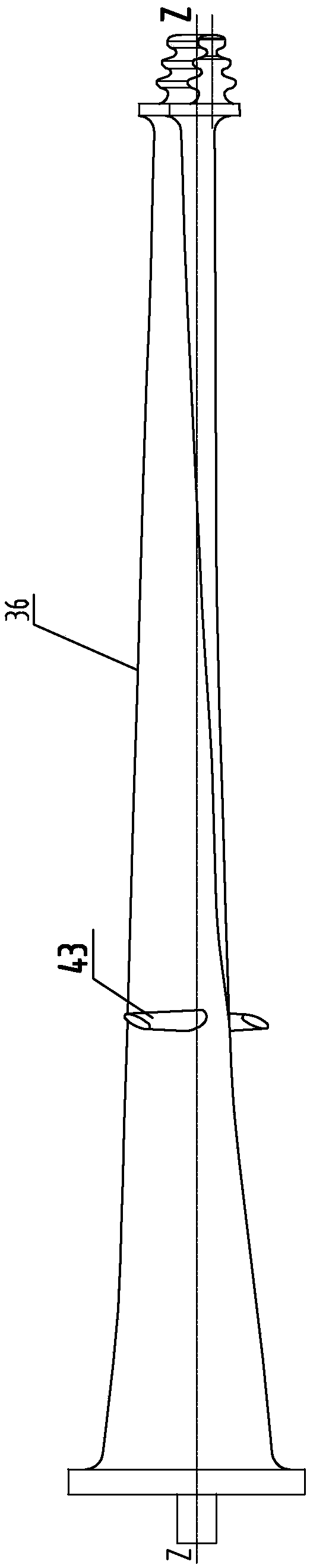
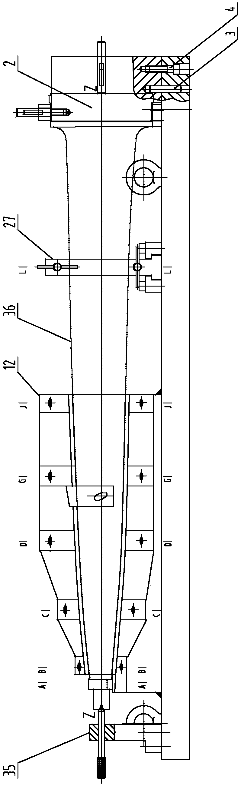
[0031] Specific implementation mode one: combine Figure 1 to Figure 15 Describe this embodiment, this embodiment includes bottom plate 1, blade root positioning seat 2, L profile line positioning block 27, profile line positioning seat 12 and blade crown thimble seat 35, described bottom plate 1 is horizontally set, and described blade root positioning Seat 2, L profile line positioning block 27, profile line positioning seat 12 and leaf crown thimble seat 35 are sequentially arranged on base plate 1 along the length direction of base plate 1, and large blade 36 is arranged on blade root positioning seat 2, L profile profile line Between the positioning block 27, the molded line positioning seat 12 and the leaf crown thimble seat 35, the leaf crown portion 46 of the large blade 36 is pressed against the leaf crown thimble seat 35, and the tendon type line section 47 of the large blade 36 is in phase with the profiled line positioning seat 12. Cooperate with the setting, the a...

specific Embodiment approach 2

[0037] Specific implementation mode two: combination image 3 , Figure 4 and Figure 12 To illustrate this embodiment, the blade root positioning seat 2 is detachably connected to the bottom plate 1 through the blade root positioning assembly. The clamping shaft 11 on the air outlet side, the end of the blade root positioning seat 2 facing the profile line positioning block 27 is processed with a placement groove for the blade root, and the bottom of the blade root positioning seat 2 is detachably connected to the bottom plate 1 through the air intake side positioning block 8, The top of the blade root positioning seat 2 is provided with a blade root outlet side wedge 10 and an outlet side pressure plate 9 sequentially from top to bottom, and the blade root air outlet side clamping shaft 11 passes through the blade root air outlet side wedge 10 and tightens on the air outlet side pressure plate 9 on.

[0038] The structural design of the blade root positioning seat 2 in th...

specific Embodiment approach 3

[0039] Specific implementation mode three: combination image 3 , Figure 4 and Figure 12 To illustrate this embodiment, the bottom of the L profile line positioning block 27 is connected to the base plate 1 through the fixed pressing block 28, and the fixed pressing block 28 is processed with a T-shaped groove that matches the bottom of the L profile line positioning block 27. The bottom of the profile line positioning block 27 is slidably matched with the T-shaped slot. One side of the L profile line positioning block 27 is an arc side, and the arc side of the L profile line positioning block 27 is detachably connected with an L profile line pressing plate. 31. The arc-shaped side of the L-shaped line positioning block 27 and the L-shaped line pressing plate 31 are respectively clamped on both sides of the airway-shaped line segment 48 of the large blade 36.

[0040] In the present embodiment, the bottom of the L profile line positioning block 27 is slidably matched with ...


PUM


Abstract

The invention discloses a shaping tool for large blade heat treatment. Large blades of a steam turbine can generate deformation and internal stress in machining of air way molded lines and welding ofStellite alloy sheets, so that the quality requirements of the blades are difficult to meet, no working allowance caused by appearance of steam ways in the blades in finishing is generated, the rebound caused by internal stress in the blades in blade assembly is generated, and the blade crown assembly requirements cannot be met in blade assembly. Blade crown parts of the large blades are ejected against blade crown thimble bases; molded line segments of the large blades are matched with molded line positioning bases; air way molded line segments of the large blades are arranged on L-gear molded line positioning blocks; blade root parts of the large blades are clamped on blade root positioning bases; and molded line positioning end surfaces matched with tiepiece molded line segments of thelarge blades are formed among A# molded line pressing end surfaces, B# molded line pressing end surfaces, C# molded line pressing end surfaces, D# molded line pressing end surfaces, G# molded line pressing end surfaces, J# molded line pressing end surfaces and split positioning end surfaces. The shaping tool for large blade heat treatment is used for positioning the large blades.

Description

technical field [0001] The invention specifically relates to a heat treatment shaping tool for large blades. Background technique [0002] There are many types of steam turbine blades, among which the large blade with an air passage length of 1375mm will produce large deformation and internal stress when processing the air passage profile and welding the Stellite alloy sheet, especially the rib boss and the entire Stellite alloy The deformation of the welding part of the blade is relatively large, and the quality requirements of the blade are not met during the blade inspection, and there is no machining allowance for the air passage of the blade during finishing machining. Due to the internal stress inside the blade, springback occurs during blade assembly and even The shroud assembly requirements cannot be met. This requires blade profiling and internal stress removal. Therefore, solving the deformation of the blade after machining and removing the internal stress is the...

Claims


Application Information

Patent Timeline
Patent Type & Authority Patents(China)
IPC IPC(8): C21D9/00
CPCC21D9/0068
Inventor 王海东黄兴军贾泽李铁成王玉君徐艳李雅武贺佰仲
Owner HARBIN TURBINE
Why Eureka
Try Eureka