
Three-port direct-current converter device and hybrid modulation method and closed loop control method thereof

A DC converter and three-port technology, applied in the direction of converting DC power input to DC power output, output power conversion device, control/regulation system, etc., can solve problems such as complex implementation, limited control accuracy, and cost increase, and achieve Realize power flow control, realize output voltage regulation, and save MOS tube effect

Active Publication Date: 2015-03-25
YANGZHOU UNIV
View PDF5 Cites 8 Cited by
  • Summary
  • Abstract
  • Description
  • Claims
  • Application Information

AI Technical Summary

Problems solved by technology

When realizing the topology selection of multi-energy input power converters, in order to realize the energy transfer between different ports, the number of power tubes is usually increased to realize energy flow, which leads to complex structure of the converter, increased cost, complicated control and reduced reliability
Phase-shifting PWM is mostly implemented with analog circuits and DSP and FPGA. These methods have disadvantages such as complex implementation, limited control precision and single control function.

Method used


Image

  • Three-port direct-current converter device and hybrid modulation method and closed loop control method thereof
  • Three-port direct-current converter device and hybrid modulation method and closed loop control method thereof
  • Three-port direct-current converter device and hybrid modulation method and closed loop control method thereof

Examples


Embodiment Construction

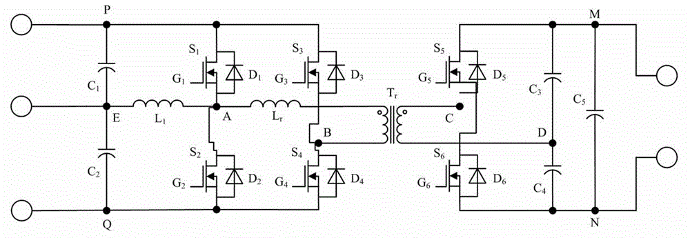
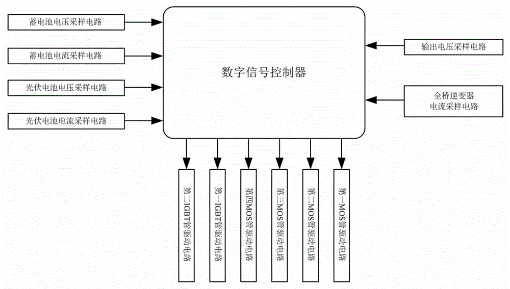
[0026] Such as Figure 1-2 A three-port DC converter device shown includes a main circuit and a control circuit:

[0027] The main circuit includes a dual-input full-bridge inverter, a high-frequency transformer, a half-bridge fully-controlled rectifier and a voltage stabilizing capacitor C 5 ;

[0028] The main circuit includes a double-input full-bridge inverter, a high-frequency transformer, a half-bridge fully-controlled rectifier and a voltage stabilizing capacitor. The dual-input full-bridge inverter includes a port P-E, a port E-Q, a port A-B, and a filter capacitor C 1 , filter capacitor C 2 , inductance L 1 , the first MOS tube S 1 , the second MOS tube S 2 , the third MOS tube S 3 and the fourth MOS tube S 4; The dual input terminals of the dual-input full-bridge inverter are the battery terminal P-E and the photovoltaic battery terminal E-Q respectively. The electrode point E, the negative electrode of the photovoltaic cell is connected to the electrode poi...


PUM


Abstract

The invention discloses a three-port direct-current converter device and a hybrid modulation method and closed loop control method of the three-port direct-current converter device. The direct-current converter device comprises a main circuit and a control circuit, wherein the main circuit comprises a double-input full-bridge inverter, a high-frequency transformer, a half-bridge full-control rectifier and a voltage stabilization capacitor; the control circuit comprises a storage battery voltage sampling circuit, a storage battery current sampling circuit, a photovoltaic battery voltage sampling circuit, a photovoltaic battery current sampling circuit, a full-bridge inverter current sampling circuit and an output voltage sampling circuit, the output end of the storage battery voltage sampling circuit, the output end of the storage battery current sampling circuit, the output end of the photovoltaic battery voltage sampling circuit, the output end of the photovoltaic battery current sampling circuit, the output end of the full-bridge inverter current sampling circuit and the output end of the output voltage sampling circuit are connected to a digital signal processor, and the signal output end of the digital signal processor is connected with a first MOS transistor driving circuit, a second MOS transistor driving circuit, a third MOS transistor driving circuit, a fourth MOS transistor driving circuit, a fifth IGBT driving circuit and a sixth IGBT driving circuit. According to the three-port direct-current converter device, cost is saved, and the three-port direct-current converter device can be used in electrical equipment.

Description

technical field [0001] The invention relates to a DC converter, in particular to a multi-input DC converter. Background technique [0002] The multi-input power converter, as a new type of power electronic conversion device, effectively combines new energy and energy storage elements, and improves the power density, reliability and transient response speed of the converter. As a new energy source with many developments and applications, photovoltaic cells have unstable and discontinuous power supply voltages, which vary with climate and weather conditions, and the maximum power output is directly affected by the intensity of light. Photovoltaic cells are used as input energy sources and integrated with energy storage components. The multi-input power converter uses energy storage elements to regulate power when the photovoltaic output changes, so that the photovoltaic cells can work at the optimal operating point while ensuring the load demand. When realizing the topology s...

Claims


Application Information

Patent Timeline
Patent Type & Authority Applications(China)
IPC IPC(8): H02M3/335H02M3/156
CPCH02M3/156H02M3/33515H02M3/33523H02M3/3353H02M3/33576H02M3/33584H02M3/33592Y02E10/56
Inventor 蒋伟于方艳
Owner YANGZHOU UNIV
Learn More