Biogas generation method of biogas generation system with strain distribution achieved under driving of biogas slurry flowing promoted by air pressure

A biogas and biogas slurry technology, applied in the field of biogas, can solve the problems of poor self-circulation effect of biogas slurry, uneven distribution of bacteria, short fermentation route, etc., and achieve the effects of long fermentation route, crust prevention and high gas production rate

Inactive Publication Date: 2015-04-01
潘磊
View PDF4 Cites 0 Cited by
  • Summary
  • Abstract
  • Description
  • Claims
  • Application Information

AI Technical Summary

Problems solved by technology

[0004] The technical problem to be solved by the present invention is that the fermentation route in the biogas fermentation system is short, the biogas slurry self-circulation effect is poor, and the uneven distribution of bacteria in the biogas slurry affects the gas production rate

Method used


Image

  • Biogas generation method of biogas generation system with strain distribution achieved under driving of biogas slurry flowing promoted by air pressure
  • Biogas generation method of biogas generation system with strain distribution achieved under driving of biogas slurry flowing promoted by air pressure
  • Biogas generation method of biogas generation system with strain distribution achieved under driving of biogas slurry flowing promoted by air pressure

Examples


Embodiment Construction

[0024] The technical solutions in the embodiments of the present invention will be clearly and completely described below in conjunction with the accompanying drawings in the embodiments of the present invention. Obviously, the described embodiments are only some, not all, embodiments of the present invention. Based on the embodiments of the present invention, all other embodiments obtained by persons of ordinary skill in the art without making creative efforts belong to the protection scope of the present invention.

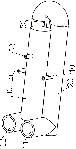
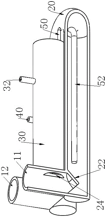
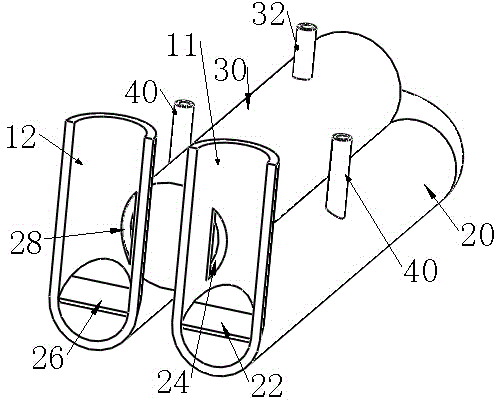
[0025] Such as Figure 1-3 As shown, the air pressure promotes the flow of biogas slurry to drive the ultra-high-efficiency biogas generation system that evenly distributes the bacteria, which includes a U-shaped fermentation pipeline 20, a feed pipe 11, and a discharge pipe 12. The feed pipe 11 and the discharge pipe 12 are arranged in the U The two ends of the U-shaped fermentation pipeline 20 are placed adjacent to each other, and the water pressure room 30 i...


PUM


Abstract

The invention discloses a biogas generation method of a biogas generation system with strain distribution achieved under driving of biogas slurry flowing promoted by air pressure. The biogas generation method comprises the following steps that fermentation raw materials are poured into a U-shaped fermentation pipeline through a feeding pipe for fermentation, so that biogas is generated, the biogas is gathered in a space between a feeding pipe gas blocking plate and a discharging pipe gas blocking plate in the U-shaped fermentation pipe, and the biogas occupies the space in the fermentation pipe and squeezes biogas slurry in the fermentation pipe to flow into a drainage pipe for the feeding pipe, a discharging pipe and a strain distribution device and then flow into a water pressure chamber through a drainage hole of the discharging pipe, a drainage hole of the feeding pipe and a drainage pipe of the strain distribution device; when the biogas stored in the fermentation pipe is delivered to the outside through a gas collection pipe, the pressure of the biogas in the fermentation pipe is lowered, the biogas slurry stored in the water pressure chamber flows back into the fermentation pipe through the drainage hole of the discharging pipe, the drainage hole of the feeding pipe and the drainage pipe of the strain distribution device, and then circulating flowing of the biogas slurry is achieved.

Description

technical field [0001] The invention relates to the technical field of biogas, in particular to a biogas fermentation system. Background technique [0002] China's biogas originated in the 1970s and has a development history of nearly 40 years. It has experienced three stages of ups and downs. From 1971 to 1981, it was a stage of rapid development and decline; from 1981 to 1991, it was a stage of adjustment and emphasis on technology; 1991 The period from 2000 to 2000 is the stage of recovery and the benefits are highlighted; the period from 2001 to 2009 is the stage of comprehensive improvement and rapid development; after 2009, it tends to fall back. [0003] Looking back at the ups and downs of biogas development in China, we have fully analyzed the existing problems of biogas (household use) in China: 1. The structure of the biogas fermentation part is unreasonable, and the current promotion is still the pool type fermentation system in the 1980s , It is difficult to fe...

Claims


Application Information

Patent Timeline
Patent Type & Authority Applications(China)
IPC IPC(8): C02F11/04
CPCC02F11/04C02F2303/06Y02E50/30
Inventor 潘磊
Owner 潘磊
Why Eureka
Try Eureka