Composite material substation structure

A composite material and substation technology, which is applied in the field of composite substation structure, can solve the problems of poor lightning protection and earthquake resistance, large frame height and width, and large occupied area, so as to reduce the size of electrical layout and reduce the occupied area , the effect of long operating life

Inactive Publication Date: 2015-04-01
中国能建集团装备有限公司南京技术中心 +1
View PDF8 Cites 9 Cited by
  • Summary
  • Abstract
  • Description
  • Claims
  • Application Information

AI Technical Summary

Problems solved by technology

[0003] The purpose of the present invention is to provide a composite substation frame, which solves the problems that traditional steel and concrete frames require long in

Method used


Image

  • Composite material substation structure
  • Composite material substation structure
  • Composite material substation structure

Examples


Embodiment 1

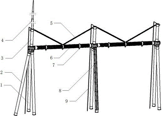
[0024] Embodiment one: if Figure 1 to Figure 7 , Figure 10 As shown, the composite material substation frame provided by the embodiment of the present invention, the main frame structure includes a composite material pipe member herringbone column 1, end support 2, beam 6, ground wire column 3, diagonal stay rod 5, and wire hanging pipe clamp 7, Hanging line pipe clamp 7 comprises two semicircular hoops, and the two ends are respectively connected by hinged bolts 10, wherein one end of one piece is integrally or separately suspended with an extended hanging line plate 11.

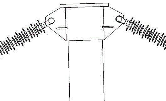
[0025] The herringbone column 1 includes the top connector of the herringbone column and the column body of the herringbone column. The ground wire column interface and the beam interface are respectively connected to the column body of the herringbone column through the top connector of the herringbone column. The top connector of the herringbone column is A trapezoidal structure, the trapezoidal struct...

Embodiment 2

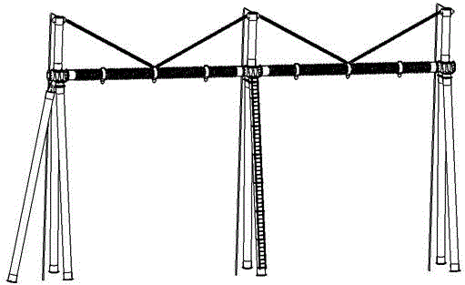
[0028] Embodiment two: see in conjunction with Figure 8 to Figure 9 As shown, the beam 6 of the embodiment of the present invention is replaced by a composite material lattice beam, and the structure of the connector at the top of the herringbone column is changed to be suitable for the installation of the frame beam, forming the second embodiment of the present invention. The implementation manners of the embodiments are the same and will not be repeated here.


PUM


Abstract

The invention provides a composite material substation structure. The composite material substation structure comprises herringbone columns, cross beams, ground wire columns, diagonal draw bars, wire hanging tube clamps, lightning rods, lightning conductors and crawling ladder assemblies, wherein ground wire column connectors are arranged on the tops of the herringbone columns, and cross beam connectors are arranged on the two sides of the herringbone columns; one ground wire column is mounted on the top of each herringbone column; one cross beam is connected between the two herringbone columns; the tops of the ground wire columns are connected with the wire hanging tube clamps in the middle parts of the cross beams through the diagonal draw bars; one or more cable-stayed structural gantry frames are formed; the wire hanging tube clamps mounted on the cross beams serve as wire hanging point connectors, the wire hanging tube clamps are made of rolled steel, aluminum alloy or a non-metallic composite material, and the herringbone columns, the cross beams, the ground wire columns, the diagonal draw bars and the crawling ladders are made of non-metallic composite materials; insulators are shortened through the structure, the height and width of the structure are reduced, and thus the floor area is reduced, and the lightning protection and earthquake prevention effects are improved; meanwhile, the land expropriation cost of an engineering project can be reduced, the reliability of safe operation is improved, and the resources are saved.

Description

technical field [0001] The invention relates to a composite material frame, in particular to a composite material substation frame. Background technique [0002] With the development of the power grid, there has been a grid construction pattern of national networking and power transmission from west to east. At the same time, the development of new energy and smart grids has promoted the construction of power grids. With the rapid development of power grid technology, there are more and more substation projects, and the demand for steel is also increasing. At present, most substation structures use steel structures or concrete structures, which have problems such as heavy weight, difficult construction, transportation, and operation and maintenance. Especially In high-voltage substations, there are shortcomings and deficiencies such as heavy substation frame structure, complicated processing and molding, high cost, and difficult construction. Contents of the invention [...

Claims


Application Information

Patent Timeline
IPC IPC(8): E04H5/04
CPCE04H5/04
Inventor 周青鲁加明陆桂来李若谷龚俊
Owner 中国能建集团装备有限公司南京技术中心
Why Eureka
Try Eureka